This thread has been locked.

If you have a related question, please click the "Ask a related question" button in the top right corner. The newly created question will be automatically linked to this question.

BQ79718-Q1: BQ79718-Q1 Sleep Mode Fault Tone

Part Number: BQ79718-Q1

Hi

The customer design with BQ79718-Q1, they test the SM_SLEEP_FAULT: Sleep Mode Fault Tone following the Safety Manual.

They set the fault tone registers according to the manual, but the expected diagnostic result did not appear. In addition, they set the heartbeat fault, and the diagnosis result is correct.

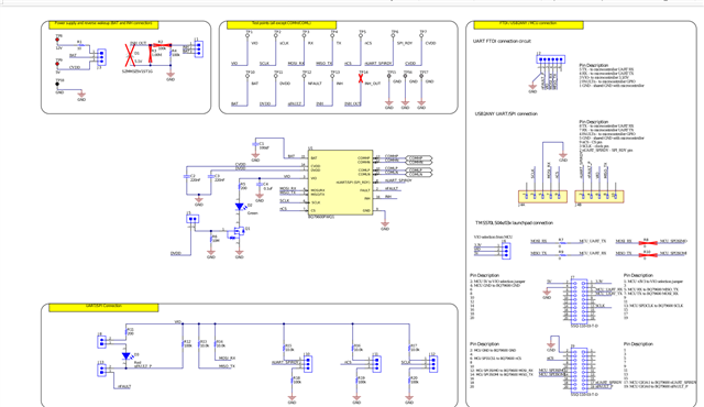
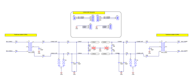
The base device is bq79600, connected with four BQ79718-Q1, and uses a ring architecture.

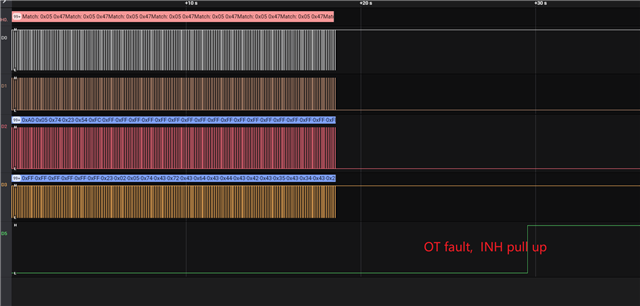
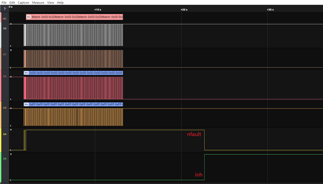
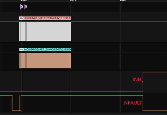
They let the base and stack devices in sleep mode and set the OVUV fault on the stack. They found the nfault pin of the base device was not pulled down.

Attached the waveform.

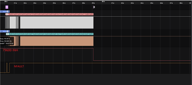
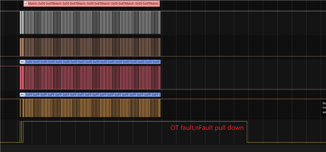
Disconnect the daisy chain, and set the heartbeat fault, then found the nfault pin of the base device is pulled low

The register setting as below:

                           1.BQ79718  FAULT_MSK1= 0xE7u,FAULT_MSK2= 0xF3u; FAULT_RST1= 0xFFu ,FAULT_RST2= 0xFFu
                           2.Set BQ79718  DEV_CONF1= 0x2Fu, enable FTONE_EN, NFAULT_EN, HB_EN
                           3.BQ79600 FAULT_MSK= 0xE7u; FAULT_RST= 0xFFu
                           4.Set BQ79600 DEV_CONF1= 0x35u, DEV_CONF2= 0x11u;  then set DEV_CONF2= 0x00u,FAULT_RST= 0xFFu

Please help check it.

Thanks

Star

  • Hi Star,

    Can you please send the customer's schematic showing the ring architecture with all 4 stack devices and the base device? 

    Additionally, I noticed that the INH pin starts HIGH in the first waveform, then it transfers LOW.  Does the INH pin always start HIGH for the customer when they are using all 4 stack devices?  It starts LOW when the customer has disconnected the daisy chain and the NFAULT pin is correctly signaling a voltage fault.

    Best,

    Andria

  • Hi Andria

    Thanks for your reply.

    The  ring architecture as follow.

    79600COMMH→COMML 79718 COMMH→COMML 79718 COMMH→COMML 79718 COMMH→COMML 79718 COMMH→  COMML79600

    INHpin does not start from high every time. It starts from high because the last fault was not cleared during reset.

    When they disconnect the daisy chain, the INH output high and NFAULT output low.

    However, the same phenomenon does not occur when the stack device set OVUV fault.

    Waiting for your reply.

    Thanks

    Star

  • Hi Star,

    Thank you for clarifying the INH status.

    Can you please send the customer's schematic if possible?  I would like to see their exact connections for communication.

    Best,

    Andria

  • Hi Andria

    Thanks for your reply.

    Attached the communication schematic.

    Thanks

    Star

  • Hi Star,

    I recommend that the customer replaces the 100 pF bypass capacitors with 220 pF capacitors (C9, C10, C11, C12).

    Additionally, has the customer observed the NFAULT pin pulling down if there is a temperature or current fault in the stack?  Are all faults failing to be recognized, or just voltage faults?

    Finally, what is the value for the 718's FAULT_SUMMARY register when the customer is placing the device in OVUV conditions?  Is the FAULT_OVUV flag set?

    Best,

    Andria

  • Hi Andria

    Thanks for your help. 

    The customer only tested the voltage fault, the temperature fault has not been tested yet,  the current fault detection 718 does not support.

    Read the FAULT_SUMMARY register of 718 in active mode, the values ​​are 0x02, 0x02, 0x02, 0x10.

    The device test the UV faults only set the FAULT_OVUV flag, the other register set the FAULT_COMM flag.

    Waiting for your reply.

    Thanks

    Star

  • Hi Andria

    The customer test the OT FUALT, the capacitors C9, C10, C11, C12 are not replaced, the nfault pin will be pulled down and the inch will be pulled up.

    They retested the UV fault again.

    When the device in sleep mode, they changed the power supply voltage to 20V (the under voltage threshold is 1200mV, 18 channels) set the stack device under voltage. The nfault pin will be pulled down and the inch will be pulled up.

    When the device in sleep mode, they disconnect the sampling resistance of some channels to make an under voltage fault (by switching the Resistor Ladder switch on the evm board), and the nfault pin will not be pulled down, nor will the inch be pulled up. Why?

    Waiting for your reply.

    Thanks

    Star

  • Hi Star,

    To ensure I have this correct:

    • The customer has found that OVUV protection DOES pull the NFAULT pin low, INH p[in DOES go high, and a flag is registered in the FAULT_SUMMARY register, but this only happens when the customer reduces the voltage across ALL cells. 
    • If the customer tries to create an OVUV fault by switching the resistor ladder switch, then the NFAULT pin does NOT pull low, INH does NOT go high, and there is not a flag in the FAULT_SUMMARY register.
    • OT conditions cause the NFAULT pin to be pulled low and INH to go high.

    If this is the case, then have the customer continue to test OVUV faults by altering the power supply voltage for now. 

    I will look into exactly why altering the resistor ladder switches changes OVUV detection and respond to this thread in another post soon.

    Best,

    Andria