This thread has been locked.

If you have a related question, please click the "Ask a related question" button in the top right corner. The newly created question will be automatically linked to this question.

BQ25790: Questions

Part Number: BQ25790

Hi team,

Could you please answer to below quesitons?

1. During battery voltage 8.0~8.2V (2cell), there are switching frequesncy transistion from 1.5MHz to 750kHz. While this transistion, can customer reduce ripple?

2. When /CE is H, how much the VBUS current? (= quiescent current when no switching)

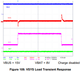
3. Customer can not see the same behavior with datasheet page 121 figure 109. What is expected? Measurment point is SYS pin, SYS pin are connected to e-load, and BAT pin are connected to 2 cell battery.

Regards,

Hayashi

  • Hi Hayashi-san,

    Regarding 1, when VBUS is close to VBAT, the converter enters buck-boost mode.  The converter first reduces the fsw to 1/2 of the buck(boost) FETs for a brief time depending on whether VBUS  > or < VBAT. Then the boost(buck) FETs start switching at 1/2 the fsw as well.  So eventually the buck and boost FETs are interleaved for an equivalent full fsw.  Unfortunately this buck-boost operation when VBUS ~= VBAT cannot be changed.

    Regarding 2, with PFM on and VBAT=8V, VBUS=15V, Iq~=5mA and VBUS=~7mA.

    Regarding 3, with charge disabled, PFM disabled and input current limit set high enough to provide the desired output power, the customer's transient should be the same as below:

    Regards,

    Jeff