This thread has been locked.

If you have a related question, please click the "Ask a related question" button in the top right corner. The newly created question will be automatically linked to this question.

LM26420: Dual buck converter IC LM26420YMH/NOPB to get 3.3V and 1.2V DC from 5VDC input

Part Number: LM26420
Other Parts Discussed in Thread: TPS62442

Hello Sir,

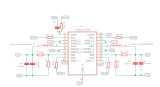
I am using a Dual buck converter IC LM26420YMH/NOPB to get 3.3V and 1.2V DC from 5VDC input.

3.3V & 1.2VDC The output looks unhealthy,

Initially, Outputs are varying randomly on 1.2V and 3.3VDC Output, but on 3.3VDC the output settles at 3.4VDC & but on 1.2VDC  the output varies continuously from 1.28 VDC  to 4.6VDC .

Can you please let me know, What will be the reason behind it?

Does this IC require a minimum load required to get stable output?
Please correct any mistakes are there in the schematic or Component selection.

Looking forward to your reply.

Regards
Murthy

  • Hi Murthy,

    I will review the schematic and get back to you tomorrow.

    Regards,

    Febin

  • Hi Murthy,

    - Most of the schematic looks fine.

    However, the additional filtering required on VINC is not clear. Do you have any filter for this pin? 

    Secondly, I could not find any input capacitors. 

    -You don't need any minimum load to get a stable output. 

    -Could you share scope plots when the device behaves abnormally? Please include Vin, Vout, SW, FB pin waveforms for both rails.

    -What is the load for each rail?

    -Could you please share the layout?

    -How many boards have you tested?

    -Is this a new application design or an existing one? 

    I recommend using our latest dual converter in new designs, TPS62442. You will benefit from both cost and performance with our latest devices.

    Regards,

    Febin

  • Hello Sir,
    Please find my reply below in red

    Most of the schematic looks fine.
    Okay, Sir.

    However, the additional filtering required on VINC is not clear. Do you have any filter for this pin?
    Yes, I shorted R25, There is no RC filter used in Testing.

    Secondly, I could not find any input capacitors.
    But in testing actually, I have kept 22uF, Two Capacitors in parallel at the Input.

    -You don't need any minimum load to get a stable output.
    Okay, Sir.

    -Could you share scope plots when the device behaves abnormally? Please include Vin, Vout, SW, and FB pin waveforms for both rails.
    I will share those waveforms shortly.

    -What is the load for each rail?
    For Testing, I am using 10 Ohm Resistive Load on both 1.2V DC and 3.3V DC.

    -Could you please share the layout?
    please share your email ID, I will share it over email.

    -How many boards have you tested?
    Two Boards.

    -Is this a new application design or an existing one?
    The new one, But we have manufactured 10 no's.

    I recommend using our latest dual converter in new designs, TPS62442. You will benefit from both cost and performance with our latest devices.
    I got it, I will use TPS62442 in my Next revision, but help me to resolve the current Issue.

    TPS62442 This part is not stocked. I think.

    Regards,
    Murthy

  • Hi Murthy,

    Please send to febin.hameed@ti.com

    Regards,

    Febin