Other Parts Discussed in Thread: TINA-TI
Hello,
I am using UCC28701 to design a 20V/2A output flyback with a switch frequency around 100kHz.
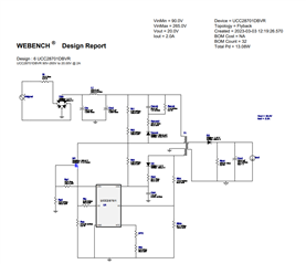
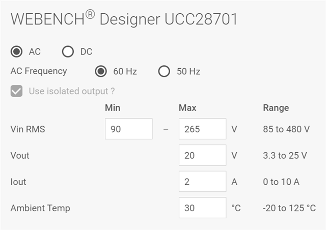
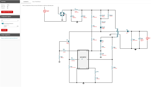
I downloaded its TINA-TI model from website and used the WEBENCH Designer shown below to design the system.

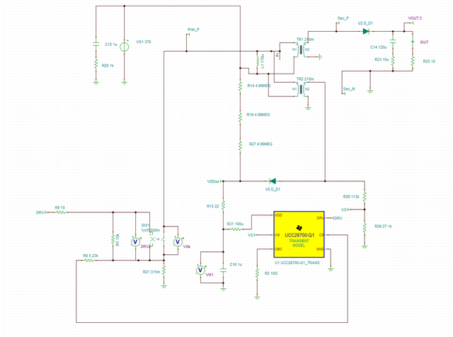
The WEBENCH gives a detailed schematic design shown below and I copied all these parameters into the TINA-TI to do the simulation.
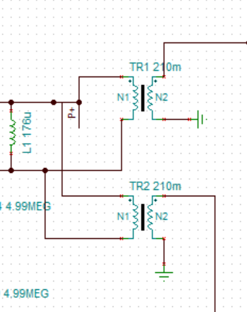
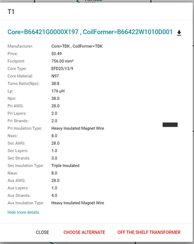
(Transformer info generated by WEBENCH is also attached.)
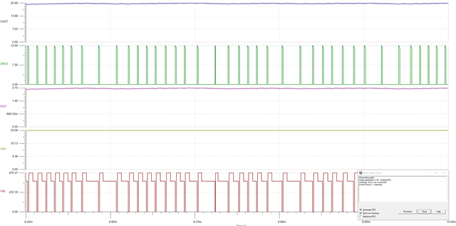
However, the simulation shows that the gate signal provided to device is not constant and lower than 100kHz.
I understand that the simulation may not 100% match with the calculation. But the variable frequency is what confused me.
I am not sure whether this is a TINA-TI simulation setting issue or not.
The DRV2 signal in the following figure is the gate signal sent to device.
The simulation file is also attached.
My question is that: Which result should I trust?
The TINA-TI simulation result or the design generated by WEBENCH POWER DESIGNER?
Thanks for your help.