Hi,
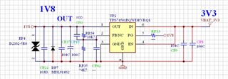
I'm gonna use TPS74501PQWDRVRQ1 from TPS745-Q1 series
but before that i want to test LDO PSRR, from the document i found there is 3 method to test PSRR :
1. Measuring using LC Summing Node Method
2. Summing Amplifier
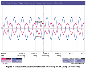
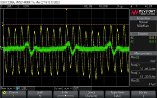
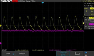
3. by Oscilloscope (40dB - 50dB)
from this option method, i would like to test our LDO using Oscilloscope which is more easier and it match our LDO series (Ours only 45dB which it can be measured by Oscilloscope)
but i have several question :
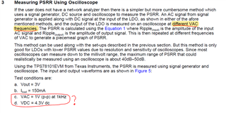
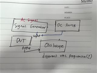
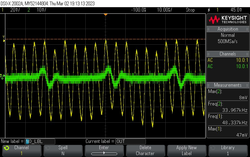
A. what is the meaning of different VAC frequencies?
B. how to set the right value for VAC and VDC ?
Thank you