This thread has been locked.

If you have a related question, please click the "Ask a related question" button in the top right corner. The newly created question will be automatically linked to this question.

BQ34Z100-G1: Single LED SOC interface not as documented. v0.16 in use

Part Number: BQ34Z100-G1
Other Parts Discussed in Thread: BQSTUDIO, BQ34Z100

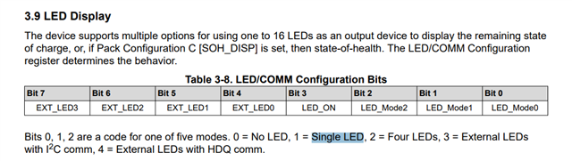
This part has SOC indication that can be multiple LEDs or a single LED. The documented single LED scheme is here (out of SLUSBZ5D pg.39):

  "  Single LED mode—Upon detecting an A/D value representing 2.5 V on the VEN pin, Single LED mode will
toggle the LED as duty cycle on within a period of 1 s where each 1% of RSOC is a 7.8125-ms high time. So,
for example, 10% RSOC or SOH will have the LED on for 78.1 ms and off for 921.9 ms. 90% RSOC or SOH will
have the LED on for 703.125 ms and off for 296.875 ms. Any value > 90% will display as 90%.  "  

The part does not do this.

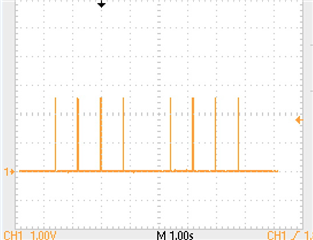
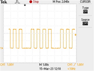
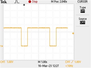
We see 0 to 100% duty cycle signal with a period of 800 milliseconds, for 4 cycles, and then no signal for one 800 millisecond "period".

This entire waveform repeats with a total period approaching five seconds. Having designed a low pass filter around the documented specification to create a voltage indicating SOC, we may find it necessary to increase further our time constants and our settling time, if we cannot find a configuration that will follow the part's documentation.

  • Hello Ken,

    Can you share the scope captures of the different SOC values and their corresponding duty cycles? Also please share your srec and .gg file. When you attached BQStudio the gauge is auto detected? (you shouldn't need to manually select it)

    Sincerely,

    Wyatt Keller

  • I get this trying the export *.gg.csv

    Have not done the learning cycle yet with QEN on. (need to rediscover where those instructions are). [ found in Ch.11 of SLUUBW5A ]

    Were trying to get the single LED signal to do something so turned on tracking experimentally and got the waveform described. Looks like this

    We think not all the needed parameters are being setup by the ChemID file for NiMH. Charge and discharge values remained for the LiIon defaults.Not sure what the ramifications will be.

    No indication that file uploads are working here so attempts to send the .srec seem to have failed.

  • I get this trying the export *.gg.csv

    Have not done the learning cycle yet with QEN on. (need to rediscover where those instructions are). [ found in Ch.11 of SLUUBW5A ]

    Were trying to get the single LED signal to do something so turned on tracking experimentally and got the waveform described. Looks like this at 0% State of Charge:


    3/15/23  and update to this waveform. Today during our failed learning cycle this single-LED  SoC indicator  waveform was captured. Soc was at 51% per the gauge interface and the waveform was clearly not what the part specification says it should be. Instead we have an approximately 50% duty cycle signal that drops out every fifth pulse.  There is about a 0.8 second period when clocking.  This is not what is documented in the gauge specification.


    and at 100% SoC the waveform goes to 100%, still with a dropout every "5th" cycle so it turns into an apparent 80% duty cycle at 4Hz.

    end of 3/15 update.

    We think not all the needed parameters are being setup by the ChemID file for NiMH. Charge and discharge values remained for the LiIon defaults.Not sure what the ramifications will be.

    No indication that file uploads are working here so attempts to send the .srec seem to have failed.

    The gauge is autodetected  by bqstudio at startup .

  • Hello Ken,

    I'm not familiar with this error from BQStudio, I will need to check with someone else on the team.

    The pulse frequency and duty cycle may not be correct if your settings are not configured. IT_EN would need to be set and ideally you would have used GPCCEHM and completed a learning cycle so the SOC values are correct.

    the Chem ID does not change the charge settings, when NiMH cell is uploaded we use different method for charge termination as described in the TRM and you will need to adjust them to match for specific cells, it should be the same process for setup of charge parameters if you were using Li-ion.

    Sincerely,

    Wyatt Keller

  • Hello Ken,

    Are you using the latest version of bqStudio from BQSTUDIO-TEST?

  • Hello Ken,

    We are not seeing such an error on export. Can you do a clean installation and then check?

    Steps:

    1. Delete C:\ti\BatteryManagementStudio or rename it

    2. Install Battery Management Studio

  • Cannot do that right now. Currently trying to complete a learning cycle. Then we will see what the single LED interface is doing, which is the subject of this thread.

    I was able to save a .gg.csv file this afternoon so that issue is not a concern today.  mcia.gg.csv

    the .srec files will still not upload....

    Completing a LC and the single LED interface are the concerns today.

  • Hello Ken,

    We will need the gg.csv file to check the configuration settings

  • mcia-23-3-10.gg.csv  Here it is again. thought it was up already.

    Failed again trying a learn this morning. not getting status to 05 from 04. Instructions indicate the gauge is not detecting end of charge, even though the "Cell V at Chg Term" state was updated.

  • Configuration Registers LED_Comm Configuration 1 flags

    Please check this. The bit needs to be set individually, not as a value. Use value=2

  • The instructions say Code value = 1 for Single LED. code 2 for 4 LEDs. We have a single LED.

  • Sorry, I misread it. You are right. This issue is queued for testing and may take a few days.

  • yet another few days trying to:   load chemistry; setup for NiHM;discharge to empty; let relax overnight (relaxing seems to take longer than TI thinks for NiMH cells) [Vok = 1 status = 0]; enable IT [vok = 1 status = 4]; normal charge at C/2 until voltage or temperature peak; let relax overnight [vok = 0 FC = 1 status = 4]; start discharge at C/5 [Vok =1 FC=1 status = 4 ]; continuing discharge [Vok =1 FC=0 status = 4 ];

    So the status update to 5 continues to elude us.

    * Texas Instruments Data Flash File
    * File created Tue Mar 14 08:33:16 2023
    *
    * Device Number 100
    * Firmware Version 0.16
    * Build Number not available
    * Order Number not available
    *
    * bqz Device Number 100
    * bqz Firmware Version 0.16
    * bqz Build Number 17
    *
    * Field Order: Class name, Subclass name, Parameter name, Parameter Value, Display Units
    "Configuration","Safety","OT Chg","55.0","1degC"
    "Configuration","Safety","OT Chg Time","2","Seconds"
    "Configuration","Safety","OT Chg Recovery","50.0","1degC"
    "Configuration","Safety","OT Dsg","60.0","1degC"
    "Configuration","Safety","OT Dsg Time","2","Seconds"
    "Configuration","Safety","OT Dsg Recovery","55.0","1degC"
    "Configuration","Charge Inhibit Cfg","Chg Inhibit Temp Low","0.0","1degC"
    "Configuration","Charge Inhibit Cfg","Chg Inhibit Temp High","55.0","1degC"
    "Configuration","Charge Inhibit Cfg","Temp Hys","5.0","1degC"
    "Configuration","Charge","Suspend Low Temp","-5.0","1degC"
    "Configuration","Charge","Suspend High Temp","55.0","1degC"
    "Configuration","Charge","Pb Temp Comp","24.960","%"
    "Configuration","Charge","Pb Reduction Rate","10.000","%"
    "Configuration","Charge Termination","Taper Current","100","mAmp"
    "Configuration","Charge Termination","Min Taper Capacity","25","mAmpHr"
    "Configuration","Charge Termination","Cell Taper Voltage","100","mVolt"
    "Configuration","Charge Termination","Current Taper Window","40","Seconds"
    "Configuration","Charge Termination","TCA Set %","99","Percent"
    "Configuration","Charge Termination","TCA Clear %","95","Percent"
    "Configuration","Charge Termination","FC Set %","100","Percent"
    "Configuration","Charge Termination","FC Clear %","98","Percent"
    "Configuration","Charge Termination","DODatEOC Delta T","10.0","1degC"
    "Configuration","Charge Termination","NiMH Delta Temp","3.0","1degC"
    "Configuration","Charge Termination","NiMH Delta Temp Time","180","Seconds"
    "Configuration","Charge Termination","NiMH Hold Off  Time","100","Seconds"
    "Configuration","Charge Termination","NiMH Hold Off Current","240","mAmp"
    "Configuration","Charge Termination","NiMH Hold Off  Temp","25.0","1degC"
    "Configuration","Charge Termination","NiMH Cell Negative Delta Volt","5","mVolt"
    "Configuration","Charge Termination","NiMH Cell Negative Delta Time","16","Seconds"
    "Configuration","Charge Termination","NiMH Cell Neg Delta Qual Volt","1500","mVolt"
    "Configuration","Data","Manuf  Date","2023-3-10","Day + Mo*32 + (Yr -1980)*256"
    "Configuration","Data","Ser. Num.","0005","hex"
    "Configuration","Data","Cycle Count","1","Count"
    "Configuration","Data","CC Threshold","900","mAmpHr"
    "Configuration","Data","Max Error Limit","100","%"
    "Configuration","Data","Design Capacity","1900","MilliAmpHour"
    "Configuration","Data","Design Energy","8000","MilliWattHour"
    "Configuration","Data","SOH Load I","-400","MilliAmp"
    "Configuration","Data","Cell Charge Voltage T1-T2","1500","mV"
    "Configuration","Data","Cell Charge Voltage T2-T3","1500","mV"
    "Configuration","Data","Cell Charge Voltage T3-T4","1500","mV"
    "Configuration","Data","Charge Current T1-T2","10","Percent"
    "Configuration","Data","Charge Current  T2-T3","50","Percent"
    "Configuration","Data","Charge Current  T3-T4","30","Percent"
    "Configuration","Data","JEITA T1","0","degC"
    "Configuration","Data","JEITA T2","10","degC"
    "Configuration","Data","JEITA T3","45","degC"
    "Configuration","Data","JEITA T4","55","degC"
    "Configuration","Data","Design Energy Scale","1","Number"
    "Configuration","Data","Device Name","bq34z100-G1","-"
    "Configuration","Data","Manufacturer Name","MCIA","-"
    "Configuration","Data","Device Chemistry","NiMH","-"
    "Configuration","Discharge","SOC1 Set Threshold","150","mAh"
    "Configuration","Discharge","SOC1 Clear Threshold","175","mAh"
    "Configuration","Discharge","SOCF Set Threshold","75","mAh"
    "Configuration","Discharge","SOCF Clear Threshold","100","mAh"
    "Configuration","Discharge","Cell BL Set Volt Threshold","1000","mVolt"
    "Configuration","Discharge","Cell BL Set Volt Time","2","Seconds"
    "Configuration","Discharge","Cell BL Clear Volt Threshold","1050","mVolt"
    "Configuration","Discharge","Cell BH Set Volt Threshold","1525","mVolt"
    "Configuration","Discharge","Cell BH Volt Time","2","Seconds"
    "Configuration","Discharge","Cell BH  Clear Volt Threshold","1475","mVolt"
    "Configuration","Discharge","Cycle Delta","0.05","%"
    "Configuration","Manufacturer Data","Pack Lot Code","0000","hex"
    "Configuration","Manufacturer Data","PCB Lot Code","0000","hex"
    "Configuration","Manufacturer Data","Firmware Version","0000","hex"
    "Configuration","Manufacturer Data","Hardware Revision","0000","hex"
    "Configuration","Manufacturer Data","Cell Revision","0000","hex"
    "Configuration","Manufacturer Data","DF Config Version","0000","hex"
    "Configuration","Integrity Data","Static Chem DF Checksum","6cca","Number"
    "Configuration","Lifetime Data","Lifetime Max Temp","30.0","1degC"
    "Configuration","Lifetime Data","Lifetime Min Temp","20.0","1degC"
    "Configuration","Lifetime Data","Lifetime Max Chg Current","990","mAmp"
    "Configuration","Lifetime Data","Lifetime Max Dsg Current","-344","mA"
    "Configuration","Lifetime Data","Lifetime Max Pack Voltage","291","20mV"
    "Configuration","Lifetime Data","Lifetime Min Pack Voltage","175","20mV"
    "Configuration","Lifetime Temp Samples","LT Flash Cnt","11","Count"
    "Configuration","Registers","Pack Configuration","09d9","flags"
    "Configuration","Registers","Pack Configuration B","af","flags"
    "Configuration","Registers","Pack Configuration C","37","flags"
    "Configuration","Registers","LED_Comm Configuration","01","flags"
    "Configuration","Registers","Alert Configuration","0000","flags"
    "Configuration","Registers","Number of series cell","4","num"
    "Configuration","Lifetime Resolution","LT Temp Res","1.0","1degC"
    "Configuration","Lifetime Resolution","LT Cur Res","100","mA"
    "Configuration","Lifetime Resolution","LT V Res","1","20mV"
    "Configuration","Lifetime Resolution","LT Update Time","60","Seconds"
    "Configuration","LED Display","LED Hold Time","4","Num"
    "Configuration","Power","Flash Update OK Cell Volt","1000","mVolt"
    "Configuration","Power","Sleep Current","10","mAmp"
    "Configuration","Power","FS Wait","0","Seconds"
    "System Data","Manufacturer Info","Block A 0","00","hex"
    "System Data","Manufacturer Info","Block A 1","00","hex"
    "System Data","Manufacturer Info","Block A 2","00","hex"
    "System Data","Manufacturer Info","Block A 3","00","hex"
    "System Data","Manufacturer Info","Block A 4","00","hex"
    "System Data","Manufacturer Info","Block A 5","00","hex"
    "System Data","Manufacturer Info","Block A 6","00","hex"
    "System Data","Manufacturer Info","Block A 7","00","hex"
    "System Data","Manufacturer Info","Block A 8","00","hex"
    "System Data","Manufacturer Info","Block A 9","00","hex"
    "System Data","Manufacturer Info","Block A 10","00","hex"
    "System Data","Manufacturer Info","Block A 11","00","hex"
    "System Data","Manufacturer Info","Block A 12","00","hex"
    "System Data","Manufacturer Info","Block A 13","00","hex"
    "System Data","Manufacturer Info","Block A 14","00","hex"
    "System Data","Manufacturer Info","Block A 15","00","hex"
    "System Data","Manufacturer Info","Block A 16","00","hex"
    "System Data","Manufacturer Info","Block A 17","00","hex"
    "System Data","Manufacturer Info","Block A 18","00","hex"
    "System Data","Manufacturer Info","Block A 19","00","hex"
    "System Data","Manufacturer Info","Block A 20","00","hex"
    "System Data","Manufacturer Info","Block A 21","00","hex"
    "System Data","Manufacturer Info","Block A 22","00","hex"
    "System Data","Manufacturer Info","Block A 23","00","hex"
    "System Data","Manufacturer Info","Block A 24","00","hex"
    "System Data","Manufacturer Info","Block A 25","00","hex"
    "System Data","Manufacturer Info","Block A 26","00","hex"
    "System Data","Manufacturer Info","Block A 27","00","hex"
    "System Data","Manufacturer Info","Block A 28","00","hex"
    "System Data","Manufacturer Info","Block A 29","00","hex"
    "System Data","Manufacturer Info","Block A 30","00","hex"
    "System Data","Manufacturer Info","Block A 31","00","hex"
    "Gas Gauging","IT Cfg","Load Select","3","Number"
    "Gas Gauging","IT Cfg","Load Mode","1","Number"
    "Gas Gauging","IT Cfg","Max Res Factor","50","num"
    "Gas Gauging","IT Cfg","Min Res Factor","1","num"
    "Gas Gauging","IT Cfg","Ra Filter","500","num"
    "Gas Gauging","IT Cfg","Min PassedChg NiMH-LA 1st Qmax","50","%"
    "Gas Gauging","IT Cfg","Maximum Qmax Change","100","%"
    "Gas Gauging","IT Cfg","Cell Terminate Voltage","1000","mVolt"
    "Gas Gauging","IT Cfg","Cell Term V Delta","100","mVolt"
    "Gas Gauging","IT Cfg","ResRelax Time","500","Seconds"
    "Gas Gauging","IT Cfg","User Rate-mA","0","MilliAmp"
    "Gas Gauging","IT Cfg","User Rate-Pwr","4000","mW/cW"
    "Gas Gauging","IT Cfg","Reserve Cap-mAh","0","MilliAmpHour"
    "Gas Gauging","IT Cfg","Reserve Energy","0","mWh/cWh"
    "Gas Gauging","IT Cfg","Max Scale Back Grid","4","num"
    "Gas Gauging","IT Cfg","Cell Min DeltaV","0","mVolt"
    "Gas Gauging","IT Cfg","Ra Max Delta","15","%"
    "Gas Gauging","IT Cfg","Design Resistance","42","mOhms"
    "Gas Gauging","IT Cfg","Reference Grid","4","-"
    "Gas Gauging","IT Cfg","Qmax Max Delta %","10","mAmpHour"
    "Gas Gauging","IT Cfg","Max Res Scale","32000","Num"
    "Gas Gauging","IT Cfg","Min Res Scale","1","Num"
    "Gas Gauging","IT Cfg","Fast Scale Start SOC","10","%"
    "Gas Gauging","IT Cfg","Charge Hys V Shift","40","mVolt"
    "Gas Gauging","IT Cfg","Smooth Relax Time","1000","s"
    "Gas Gauging","Current Thresholds","Dsg Current Threshold","60","mAmp"
    "Gas Gauging","Current Thresholds","Chg Current Threshold","75","mAmp"
    "Gas Gauging","Current Thresholds","Quit Current","40","mAmp"
    "Gas Gauging","Current Thresholds","Dsg Relax Time","60","Seconds"
    "Gas Gauging","Current Thresholds","Chg Relax Time","60","Seconds"
    "Gas Gauging","Current Thresholds","Cell Max IR Correct","400","mV"
    "Gas Gauging","State","Qmax Cell 0","1000","mAmpHr"
    "Gas Gauging","State","Cycle Count","0","num"
    "Gas Gauging","State","Update Status","04","num"
    "Gas Gauging","State","Cell V at Chg Term","1500","mVolt"
    "Gas Gauging","State","Avg I Last Run","-299","mAmp"
    "Gas Gauging","State","Avg P Last Run","-1131","MilliWattHour"
    "Gas Gauging","State","Cell Delta Voltage","5","mVolt"
    "Gas Gauging","State","T Rise","20","Num"
    "Gas Gauging","State","T Time Constant","1000","Num"
    "Ra Table","R_a0","R_a0 Flag","ff55","Hex"
    "Ra Table","R_a0","R_a0 0","77","Num"
    "Ra Table","R_a0","R_a0 1","75","Num"
    "Ra Table","R_a0","R_a0 2","73","Num"
    "Ra Table","R_a0","R_a0 3","71","Num"
    "Ra Table","R_a0","R_a0 4","73","Num"
    "Ra Table","R_a0","R_a0 5","79","Num"
    "Ra Table","R_a0","R_a0 6","75","Num"
    "Ra Table","R_a0","R_a0 7","69","Num"
    "Ra Table","R_a0","R_a0 8","87","Num"
    "Ra Table","R_a0","R_a0 9","110","Num"
    "Ra Table","R_a0","R_a0 10","127","Num"
    "Ra Table","R_a0","R_a0 11","136","Num"
    "Ra Table","R_a0","R_a0 12","274","Num"
    "Ra Table","R_a0","R_a0 13","431","Num"
    "Ra Table","R_a0","R_a0 14","655","Num"
    "Ra Table","R_a0x","R_a0x Flag","ffff","Hex"
    "Ra Table","R_a0x","R_a0x 0","77","Num"
    "Ra Table","R_a0x","R_a0x 1","75","Num"
    "Ra Table","R_a0x","R_a0x 2","73","Num"
    "Ra Table","R_a0x","R_a0x 3","71","Num"
    "Ra Table","R_a0x","R_a0x 4","73","Num"
    "Ra Table","R_a0x","R_a0x 5","79","Num"
    "Ra Table","R_a0x","R_a0x 6","75","Num"
    "Ra Table","R_a0x","R_a0x 7","69","Num"
    "Ra Table","R_a0x","R_a0x 8","87","Num"
    "Ra Table","R_a0x","R_a0x 9","110","Num"
    "Ra Table","R_a0x","R_a0x 10","127","Num"
    "Ra Table","R_a0x","R_a0x 11","136","Num"
    "Ra Table","R_a0x","R_a0x 12","274","Num"
    "Ra Table","R_a0x","R_a0x 13","431","Num"
    "Ra Table","R_a0x","R_a0x 14","655","Num"
    "Calibration","Data","CC Gain","10.269","mohm"
    "Calibration","Data","CC Delta","10.250","mohm"
    "Calibration","Data","CC Offset","-1478","num"
    "Calibration","Data","Board Offset","0","num"
    "Calibration","Data","Int Temp Offset","0.0","degC"
    "Calibration","Data","Ext Temp Offset","0.0","degC"
    "Calibration","Data","Voltage Divider","9087","mVolt"
    "Calibration","Current","Deadband","5","mAmp"
    "Security","Codes","Sealed to Unsealed","36720414","hex"
    "Security","Codes","Unsealed to Full","ffffffff","hex"
    "Security","Codes","Authen Key3","01234567","hex"
    "Security","Codes","Authen Key2","89abcdef","hex"
    "Security","Codes","Authen Key1","fedcba98","hex"
    "Security","Codes","Authen Key0","76543210","hex"
    

    The Cell BH and Cell BL parameters under configuration/discharge are not really documented. Are these coming into play and affecting the ability to progress to status = 5 ?    Are there some settings of config/charge termination that can be changed to make the gauge more sensitive to the normal NiMH charge termination of a voltage peak or temperature spike while under the constant current charge?   Here is what our charge look like:   23-3-13 NiMH charge.xlsx

    3/15   Did a C/10 charge last night. Got FC again, as before, but again no status update to 5. 

  • Hello Ken,

    I am assigning this thread to an expert

  •     Sorry, I'm seeing this late, can you upload a srec file for further inspection?

  • I tried previously and tried again just now.

    The e2e file upload will not accept the .srec files.

    Today I tried zipping it and that worked.:  MCIA Mar10.zip

  •     The FC bit set is not caused by VCT(valid charge termination), please set FC Set % to -1, RMFCC to 1, with this configuration, FC set would indicate valid charge termination.

        I see NI_DT and NI_DV are both set, please make sure which method is to be used for charge termination detection.

  • 3/24 update:  NiDT and NiDV we have had set during this entire time.  We  set  FMFCC and we changed the FC set % to -1 . We restarted a new attempted a learning cycle. Still no joy. Same issue status does not progress from 04 to 05 .  We do see the FCC update at then end of the full discharge during the failed learning cycle attempt, but this is of course well after the failure to see the status change during charge so it adds no progress to the learning cycle.

    3/27 the updated FCC is changing with every partial discharge/charge, now showing half of what it was last week after simply resting over the weekend. At least the indication of Max Error = 100% is quite correct.

    Need to ask:

    Why this "FC set to -1%" setup is not documented for NiMH or configured by the ChemID for NiMH  that is in use?

  •     Sorry for delay response.

        I will discuss FC set parameter with internal team mates, it should be changed for learning cycle to success for either li-ion or NiMH batteries

        If the learning still fails, please can you upload the log file, not very sure if you got a success learning cycle after 3/27

  • 4/12 .  No, still no success with the needed status changes during learning cycles. Attached are two of the failures to progress in learned status, logged from three weeks ago.

    23-3-27.csv

    23-3-23.csv

    How about our original issue with the single LED interface not acting as documented?  Has that made it out of your queue and into a lab ?

  •     From the log file, I found the total passed charge during discharge is almost ~1900mAh, however, the Qmax from the downloaded srec file is only 1000mAH, the Qmax Cell0 set in the dataflash shall be approximate to the real value, so that the Qmax update can happen.

       Also, for 23-3-24.csv and 23-3-23.csv log file, the initial DOD0 before charging is very low, which suggests the capacity is high and the battery is not discharged to empty before charging, please refer to slua903.pdf for success learning to happen

       For the single LED issue, I will need to check with Shirish on the status of the queued test

       Do you have any updates on the queued test for Single LED issue

  • You say the Qmax update can happen. We are at a loss as to why it does not happen when it is documented to happen and why the learning cycle status changes do not happen as indicated they should.

    Our discharges are to down 1v per cell under a load, which is empty for the NiMH cells. We get indications of empty status from the gauge. How low do you think we need to go.

  •     The Qmax Cell0 set in dataflash should be close to the real value, I see this parameter is set to 1000mAh in the gg file, but the actual capacity could be around 1900mAh, the gap is too high for Qmax update to happen. Please set Qmax Cell0 approximate to the real Qmax value

  • The cells are rated at 1900mAh. that is in the Design Capacity entry in the Configuration section. we are using them conservatively, and the gauge is showing FCC in the range of 1700mAh. How close does the Qmax(cell 0) need to be for it to update properly? 

  •     If Qmax Cell0 < delta Qmax, then the Qmaux update wont happen, suggest to set to 1900mAh should be appropriate.

  • There is a Qmax Cell 0 (1777 mAmpHr), a Qmax Max Delta % (10 mAmpHr), and a Maximum Qmax Change (100 %).  We do not find a delta Qmax.

    In our current try we did set the QmaxCell0 up to 1777 from 1000 making it closer to our useful capacity.

    We have had the MaximumQmaxChange set to 100% the whole time. 

    We are confused by the QmaxMaxDelta% parameter that is shown by BQstudio to have units of mAmpHr.  Would have thought that would be percent. This is at its default of 10 but is that a percentage or mAmpHr?

    Can these three parameters please be explained?

    And we find nothing in BQstudio labeled deltaQmax.

  •     Qmax Max Delta shall be a parameter with unit of percent, it should be a typo in the bqStudio, in the following cycles after update status changed to 6, it defines a upper and low limit the cap the qmax change based on the value of design capacity. Maximum Qmax Change is one of the condition that qualifies a reasonable range for New Qmax Value, if the New Qmax Value is within this range, then the new Qmax is qualified, and Qmax Cell 0 will be updated, otherwise the update to Qmax won't happen.

       Delta Qmax is the internal variable only defined in RAM, it is not accessible with bqStudio.

  • We up the QmaxCell0 closer to, and higher than our expected, ending capacity. We changed QmaxMaxDelta to 99%.  We started another learning cycle attempt with a discharge, a relaxation, and then ITenable set.  Status changed 00 to 04. After the full charge and relaxation, the status yet again remains at 04. We see FC is set, CellV@ChgTerm has updated, and FCC has updated. The chart on pg59 of SULLBW5A says we need to be seeing the status change to 05, and again we are not seeing the change at the end of charging....

  •     Have you seen VOK changed from 1 to 0 during relax?

        I still need the latest log file for further inspection if you can upload it.

  • Well we had an entered update two days ago but the forum post got lost.

    Do not ever remember seeing VOK at anything but 1.

    Over the weekend and into the first two days this week after a discharge, relax, IT enable set, charge, relax, discharge, relax, charge, relax, discharge, relax we finally got a status change to 06. Status changes are only happening at the end of a discharge and relax. At IT enable status went to 04. Status did not change to 05 until after the next discharge, and did not change to 06 until after another full charge and discharge. So this did not proceed as documented on  pg59 of SULLBW5A.

    Here is the log. However the last discharge and timing of the last status change were not recorded as the interface kit lost connection to the gauge for some reason during the recording. Re-plugging the EV interface reestablished the connection.

    23-4-23.csv

  •     I do see VOK changes from 1 to 0 at Row#3540, and Qmax PassedQ cleared at the same row, do you have a gg file logged before and after the time logged in this row, which is 14:20, 4/23/2023 showing that the update status did change or kept unchanged?  

  • no, we do not have gg file collections bracketing row 3540.

    Please explain how often we might be needing to export to this file and when. We thought the continuous log had all your information.

    So Vok is the second bit in the control status. We do see it went to 0 at line 3540. No Voltages changes are shown here anywhere near this line.  So why does Vok status change? What does this mean?

    At this same line DOD0Passed, DOD0Time, QmaxDOD , and  firstDOD all went to zero. We also see OCVtaken goes to one at the same time.  Again what does all this mean?

    This is all at about 100 minutes since the charging was terminated (at line 2122). 

    There is not enough information for us to determine the impact of any of these bits' changes, nor what the implications are toward advancing the learning status updating process as documented in SULLBW5A.  We know the gauge needs to be able to detect charging, end of charging, discharging, and end of discharging for any updating of the IT tables to happen over the life of the products. So getting the configuration to the point it can detect these things is important.

  •     Under the Menu item of Window->Preference->DataMemory, you will see a page for gg file logging, once you entered the file name you want to use for the gg files to be saved at the interval specified in the upper edit box and click apply, the gg file will be saved automatically with name you specified.

        DOD0Passed, DOD0Time QmaxDOD are refreshed for next round Qmax update, OCVTakem means that the OCV value has been acquired at this moment. with acquired OCV, the present DOD is updated, with 2 QmaxDOD and QmaxPassedQ, the Qmax is calculated.

  • We are able to start a new try today while logging and also collecting periodic .gg files.

    Please tell us the difference between "Maximum Qmax Change" (units: %) and "Qmax Max Delta %" (units: mAmpHour) in  bqStudio's section GasGauge/IT Cfg .

  •     Maximum Qmax Change is the threshold to check if the Qmax change is too large, if yes, then the newly calculated Qmax will be ignored.

        Qmax Max Delta is a percentage to Design Capacity which defines the high and low limit of the maximum allowed Qmax update.

  • 5/18

    Here is our latest log and .gg files collected during it. It shows a discharge, relaxation, IT enable, charge, and relaxation. Figure 11-2 in SLUUBW5A says we should have seen a status change to 5 at two hours into the second relaxation. Again this time we did not see the expected change.

    MCIA may18 3 hours into relax after charging no change to status 5 .zip

    5/19 am update

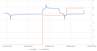
     (Blue is voltage, orange is learning status) Here we all see a discharge, a long relax, IT enable and start of charging that changes the learning status to 4. At the end of charge, and the relax that follows, the status does not change to 5 as SLUUBW5A says is expected. After a 5 hour relax, a discharge and another hour wait the status then changes to 5. Again not the expected actions. History has shown us that not until the end of another charge with relax and discharge with relax will there be a status change to 6. We will continue this test to see that repeat.

    5/20 am update

    We find again that only after the second full charge and discharge cycle do we get the status change to 6. This is not in line with Figure 11.4

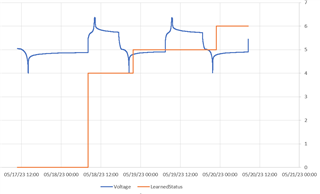
     Status only changes one hour after a discharge..

    MCIA may17 to 20 status not changing as expected.zip complete log and .gg files

  • Wyatt,

    Our thread got off track in trying to follow the steps toward a good learning cycle and ultimately a proper indication of SoC. Once we get there I am hoping to get back to the original issue and confirming that the Single LED interface in this gauge does not behave as documented.  This process is taking a long time.

  • The bq34z100 has a slightly different implementation of the Impedance Tracking algorithm, which will prevent Qmax updates after charge. It will only update Qmax after a discharge, hence you won't see Qmax update until after conditions were right after a discharge (as in your example, where status updates to 0x05 after the first full discharge). Cell resistance will only update after Qmax updated, hence you see a status update to 0x06 after the second discharge.

    Your learning cycles look correct for the bq34z100. This gauge requires two full charge/relax/discharge/relax cycles to learn both Qmax and cell resistance.

  • About the single LED:

    If single LED is enabled, the gauge will (for your configuration), perform the following:

    One tick = 7.8125ms
    One period = 100 ticks (=781.25ms)

    For a total of four periods, the gauge will, in each period:
      * turn on the LED for SOC% ticks
      * turn off the LED for 100-SOC% ticks

    If SOC > 90%, the gauge will consider this 100% for LED purposes.

    After four periods, the gauge will turn off the LED, regardless of whether it's enabled or not. If it's still enabled, it will, after a short time turn on the LED and repeat the process (hence you noticed that the gauge turned of the LED after every fourth period).

  • Thank you so much for this forum correction to the TI documentation. SLUUBW5A in Chapter 11 tells us a different tail about learning cycles for this part and was last updated in September of 2021 after first publication 3 years previously. Would it be in a queue someplace to get this documentation corrected?

  • I'll submit a bug report ticket for this document. Chapter 11 is incorrect for this particular gauge (it's correct for most other TI Impedance Tracking gauges).

  • Back to our original reason for starting this thread 3 months ago:  The single LED action also conflicts with the documented and expect behavior based on the same manual, Sec. 3.9 LED Display pg32. It says the period of the single LED is one second with a 781mSec on time representing 100% SoC. Your description of the interface aligns with the manual, but not with the behavior of the part.

    The part itself has a period closer to the 0.8 seconds, never goes off during the four periods (if representing 100%), and then goes off for one complete 0.8 second period while it updates what will be displayed. Not a short time in the scheme of things here. It would be helpful to have the manual corrected in this area too.

    We hold Ven active to get a continuous display that is then heavily filtered to provide an analog representation of state of charge without needing to use the I2C bus. This works, once corrected for actual behavior, except for the occasional time when the gauge turns off the LED for not one but two peroids during the "update" off  time. This extra off time throws the filtered analog representation off and while it happens only once every 1 to 10 hours, this maybe enough to generate concern and questions from customers. It certainly has caused concern at the bench for our desired unit functionality.  It would be great if the reason for this occasion glitch could be found and corrected.

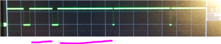
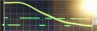
     This (green trace) attempts to show the LED on times for four periods (100%SoC) and off for one period normally, along with one instance of the off time being twice as long as normal with the filtered analog being thrown low (yellow).  [ one second per division ]

    Will this gauge require occasional two full charge/discharge cycles to update Qmax and the resistance table in the field?  Our application is such that it may not get fully discharged on a regular basis.

  • >Your description of the interface aligns with the manual, but not with the behavior of the part.

    > The part itself has a period closer to the 0.8 seconds

    My description is aligned with your observation:

    One tick = 7.8125ms
    One period = 100 ticks (=781.25ms)

    I got this information directly from reading the source code. The gauge controls the LED in an ISR which is triggered by a 7.8125ms timer. It uses a 100 ticks period (hence you observe a period closer to the 0.8 seconds).

    > never goes off during the four periods (if representing 100%), and then goes off for one complete 0.8 second period while it updates what will be displayed. Not a short time in the scheme of things here. It would be helpful to have the manual corrected in this area too.

    Yes, with SOC >90%, the LED won't turn off for four periods. And then it will turn off "for a short time" and the process repeats. I didn't profile the "short time" but what I wanted to express in my comment was the fact that the state machine that runs in the ISR controlling the LED will complete four periods and then it's back to the domain of the main process (not running in the ISR) to restart this (time = "short") as long as the conditions to turn on the "display" are still valid.

  • >Will this gauge require occasional two full charge/discharge cycles to update Qmax and the resistance table in the field?  Our application is such that it may not get fully discharged on a regular basis.

    No. The two full cycles are only required one time because the gauge requires a Qmax update one time before it will update cell resistance. Once Qmax was updated, there is no need for two extra cycles.

    Qmax will update in the field, after a discharge, if conditions are met (mostly minimum passed charge (35% of Qmax), cell voltage outside flat zone, temperature within limits (see below), voltage relaxed (or 5 hour time out)).

    "Gas Gauging","IT Cfg","Q Invalid MaxV","1301","mVolt"
    "Gas Gauging","IT Cfg","Q Invalid MinV","1225","mVolt"
    "Gas Gauging","IT Cfg","Q Invalid MaxT","40.0","1degC"
    "Gas Gauging","IT Cfg","Q Invalid MinT","10.0","1degC"

  • >This extra off time throws the filtered analog representation off and while it happens only once every 1 to 10 hours, this maybe enough to generate concern and questions from customers.

    I don't think it's possible to guarantee that the "short" time is constant. It depends on what else is going on with the gauge (the FW uses a small OS with multiple threads). The thread that controls the single LED checks the "display button" signal, de-bounces it in SW and then starts the timer for the timer interrupt. This is what causes the "short" time when the LED is off between the 4 period display "hold" time.

    It's possible to change the 4 periods up to 255 periods, which will cause the "short" LED off time to happen much less frequently (once every 255 periods instead of once ever 4 periods). It's a hidden parameter, accessible via subclass 0x43, block 0, offset 0, one byte. This may help your use case but it will still have the potential to have a bit "longer" LED off time occasionally.

  • Dominik,

    Yes you are right. The period is 100 tics and the signal does not go off when > 90%.  You do describe the behavior correctly.

    The manual unfortunately states the period is one second and says the signal does always go off every period. This too could use a correction in the manual.  The "short time" is actually one tic time, and randomly two.  The indicated SoC is only updated during this dead time.  If we toggled the input to Ven after the signalling started, would that shorten at all the dead time for the next set, or worse just randomize it ?

     We see the updated status during the learning cycles at just a little over an hour after discharge was ceased. You say Qmax will only update if the cells are left to relax for five hours in a discharged state?  Is this the only way Qmax will update in the field?

    We were looking at the implication of running for 37 or so tics (half a minute). It delays somewhat our filtered analog signal updates, which takes over a minute to settle anyway, and our cells' energy usage is around 1% a minute, so this would not be noticeable. The random extended off times might be ten times less often as well. We can try it.  Thanks for your help.

  • well this was a surprise. Changing the LED tic count from 4 to 10  shortened the "off" time substantially.

  • >The "short time" is actually one tic time, and randomly two.

    This is plausible because of how the interrupt is handled (via a HW timer) so it should be multiples of a 7.8125ms tick, depending on how the thread that restarts the process is scheduled relative to that HW timer. I don't have profiling data but what you report aligns with the code.

    >We see the updated status during the learning cycles at just a little over an hour after discharge was ceased. You say Qmax will only update if the cells are left to relax for five hours in a discharged state?  Is this the only way Qmax will update in the field?

    No. The five hour timeout is a default hard cut-off when the gauge will force an OCV measurement which eventually (other rules apply) causes a Qmax update. In a real system, if load in relax is low enough for voltage to stabilize, the gauge will not wait 5 hours but take OCV measurements and calculate Qmax as soon as the voltage is stable.

  • Dominik,

    We are finding now that the SoC indication with the single LED may only go to a minimum of one tic (7.8mSec) time on and not to zero. Can you verify this, before we add a feature to subtract from the filtered average of this signal?