This thread has been locked.

If you have a related question, please click the "Ask a related question" button in the top right corner. The newly created question will be automatically linked to this question.

BQ76952: BQ76952: BQ77216 pulling down BQ76952 CHG output

Part Number: BQ76952
Other Parts Discussed in Thread: BQ77216

Hi

I have a query need your help.

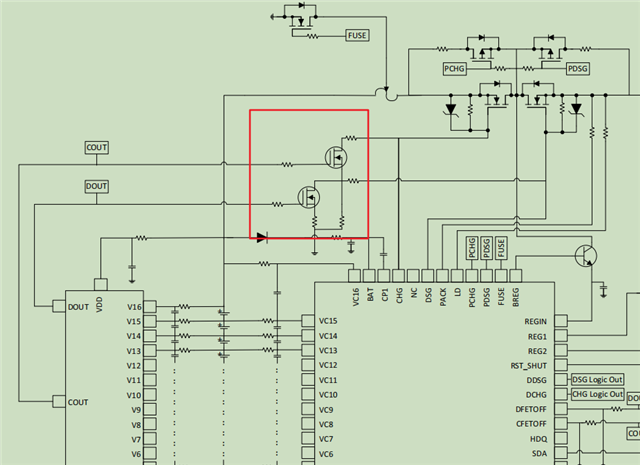
The CHG output high level of BQ76952 is Vbat+11V, and the low level is Vbat. 

After the BQ77216 is triggered, it controls the MOS in the red box and pulls the CHG of the BQ76952 to GND. How to ensure that the CHG of the BQ76952 is pulled to Vbat instead of GND.

And when BQ77216 is triggered, the CHG of BQ76952 may still output high level Vbat+11V.

Waiting for your reply.

Thanks

Star

  • Hello Star, 

    You are right, this configuration pulls down the CHG gate to GND. This is why the image you shared also shows DOUT and COUT being connected to DFETOFF and CFETOFF respectively. This ensures that the BQ779216 turns off the FET drivers of the BQ76952 and avoid discharging the charge-pump.

    The pull-down resistance must be chosen to not draw too much current from the battery.

    If they wanted to pull down the gate without using the DFETOFF/CFETOFF pins, then they would likely need additional circuitry to ensure the BQ76952 charge pump does not become discharged.

    Best Regards,

    Luis Hernandez Salomon

  • Hi Luis

    Thanks for your help.

    Does it can be connected directly like this in the picture?

    The maximum input voltage of CFETOFF pin of BQ76952 is 5.5V, while the minimum output voltage of COUT of BQ7721602 is 6V, and the IO port of MCU is generally 5V. The three signals in the above figure are directly connected together, even if FETOFF can be clamped by Zener.The DCOT pin is also connected to the IO port of the MCU, will this damage the IO of the MCU?

    Waiting for your reply.

    Thanks

    Star

  • Hello Star,

    You are correct that the recommended max for CFETOFF is 5.5-V. I've seen customers use 5-V or 5.5-V Zeners in order to limit the voltage into the pins. The figure is an example, it does not necessarily need to connect to the MCU.

    They could simply connect the same clamped voltage into the BQ76952 and the MCU through the same line.

    Best Regards,

    Luis Hernandez Salomon