This thread has been locked.

If you have a related question, please click the "Ask a related question" button in the top right corner. The newly created question will be automatically linked to this question.

TPS7H4001-SP: External Schottky Diode Current Rating

Part Number: TPS7H4001-SP
Other Parts Discussed in Thread: TPS50601A-SP,

Hello TI E2E,

     We’re trying to determine the required current rating for the external Schottky diode that connects to the Phase Node of part number Flight Part: 5962R1820501VXC, (Eng. Part: TPS7H4001HKY/EM).

We noticed in the evaluation board schematics that Diodes Inc Part number B230-13-F is used for this.

This part has a forward surge rating of 50A, and an average rectified output current of 2Amps.

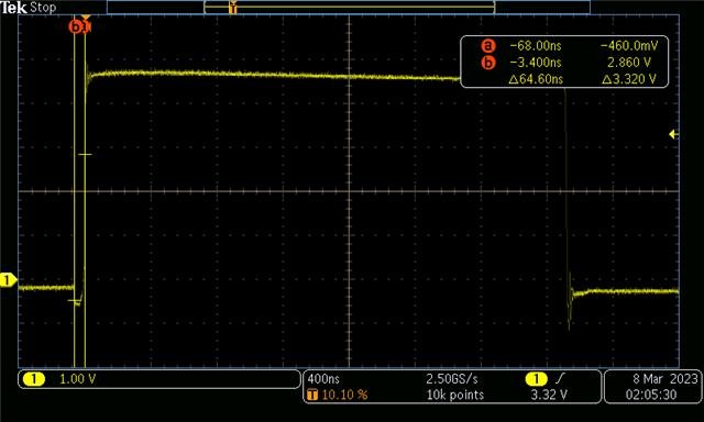
We also noticed in figure 4 of the 1master/3slave evaluation board user guide that there appears to be an interval when both the high-side & low-side fets are off (presumably to prevent shoot thru current).

See annotated figure 4 below.

If this does occur, it would seem that would leave the parallel combination of the low-side fet body diode and external Schottky diode to supply current during this interval.

Then it would seem if Vf-body diode > Vf-Schottky then most/all of output current during this interval will flow thru the external Schottky diode ?

If this is the case, should we size the external Schottky diode such that it can handle the full output current to the load ?

If this is not the case can you please explain how we should go about determining the required current rating of the external Schottky diode.


Thank you,

John Lally.

  • Hey John,

    While the case you describe where Vf-Body>Vf-Schottky is possible its rather unlikely in practice.
    Forward voltage in general tends to fluctuate with current, temperature, process, and even time when you consider the differences between the turn on times of the diodes.
    This can cause the current to split in a variety of ways that can be hard to measure at times

    In practice though, a diode that can handle surge currents greater than what you expect in your full converter is ideal as you don't have to worry about it.
    Since the time that the diode would handle the current is low, this would make the RMS current through the diode low and thus the DC forward current requirement is much lower.
    You can estimate the needed value by dividing the dead time in the circuit by the period and multiplying by the forward current in the circuit expected.

    This is why the diode in the EVM has a high surge current and a low DC current

    Thanks,
    Daniel

  • Thanks Daniel,

        When you stated "...dividing dead time in the circuit by the period..." I take it the dead time is the time when both the low-side & high-side fets are off, i.e.the interval when the schottky diode is expected to be conducting, correct? 

    If yes, how do i determine what the maximum dead time interval is, i don't see it spec'd in the data sheet or a way to calculate it.

  • Hey John,

    You are correct that the dead time is the period where both the high side and low side are off.
    We do not specify a maximum dead time interval.

    The typical value you are see from the picture you posted as its the time period where the body diode/protection diode is on.
    If I estimate it to be in the 80 ns range:
    SQRT(80 ns/ 2us period) * 18 A = 3.6 A split between the two diodes is 1.8 A per diode.

    The 18 A coming from if all the current goes through the diode, which if you look at the high to low transition is almost certainly not the case given the larger than would be expected voltage spike.

    Thanks,
    Daniel

  • Thank you Daniel,

       We have the same question for the TPS50601A-SP Buck converter, would the methodology described above apply to the TPS50601A as well ?

    If yes, what dead-time do you recommend we use for the TPS50601A-SP ? 

    If no, can you describe the methodology that applies to the TPS50601A-SP ?

    Please let us know if a separate post is needed using TPS50601A-SP and I'll do that.

  • Hey John,

    The methodology described applies to the TPS50601A-SP as well.
    I was able to take a more detailed picture for you of the PH node to ascertain the dead times:
     

    High to low transition is ~20 ns itself. Granted my comment from the TPS7H4001-SP applies here as well in which I dont believe the diode is conducting during that period due to the larger voltage.

    Thanks,
    Daniel