This thread has been locked.

If you have a related question, please click the "Ask a related question" button in the top right corner. The newly created question will be automatically linked to this question.

LMG1020EVM-006: What is your laser diode model and test method?

Part Number: LMG1020EVM-006
Other Parts Discussed in Thread: TIDA-01573, LMG1020

Hello TI engineers: 

So far, I have tested The LMG1020EVM-006 with R5-R8 . But I had to test a real laser diode to see the drive capability of the EVM.

I saw the results of your test in the manual ( TIDA-01573) and I would like to know your light source model and test method.

1. Which model of Laser Diode did your use in this experiment?

2.What is the test protocol?  (I already know that you are using Sorebo equipment, but are you directly aligning the Laser  light source with the detector and that's it?)

I would like to have a test optical path diagram or device connection diagram for reference.

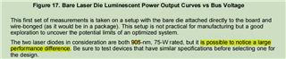
I've read the circuit plan and design information for the EVM, but there is no information about the specific laser diode type and test path for the test. So I need to ask you to help me find out if there is any relevant information. In particular, the manual mentions two 905nm, 75W laser diodes, what is the specific model of this diode? Can you provide me with a link to the manufacturer?

Looking forward to your reply!

THANK YOU!

  • Hello Haijian,

    Our team supports the gate driver IC (LMG1020), and we can answer questions about that. The TIDA is just an example of how to use the driver, we can't really support it or guarantee the best performance out of it. Designing the system is up to the end user. I will send this thread to our TIDA team, hopefully they can answer your questions.

    Thanks,

    Alex M.

  •    Hi Alex M , Thanks for your reply!

        My goal was to first restore the test conditions in the manual to achieve similar test results to those in the manual

         (mainly to see the same response rate and peak power),

         which would ensure that my driver board and light source were working properly.

        I will then base my development on this, so it is important for me to be able to restore the test conditions in the manual.

       We are looking forward to hearing from you with details of your laser light source models and  test optical path diagram.

        Thank you!

  • Hello Haijian,

    I have sent this thread to the owners of this TI design. They should hopefully be able to reply soon with more details.

    Thanks,

    Alex M. 

  •  Hi Alex M,

    Have they replyed yet?

    Thanks!

  • Hello Haijian,

    Sorry for the delay. This thread has been assigned to the owners of the TI design. That means they can reply directly to this thread; I won't have to relay information to you. 

    Thanks,

    Alex M.

  • Hello Haijian,

    Nevermind my previous response; I heard back from the engineer who designed this board.  

    1. Which model of Laser Diode did your use in this experiment?

    For a few reasons, we cannot share the exact part number. Sorry about that. A pulsed laser diode from a company like Excelitas should work well.

    2.What is the test protocol?  (I already know that you are using Sorebo equipment, but are you directly aligning the Laser  light source with the detector and that's it?)

    Yes that's all, but we did use a pipe to remove ambient lighting. 

    The point of bringing up two diodes, was to emphasize that two similarly rated diodes could deliver fairly different performance. Therefore, I see the appeal of re-creating the setup exactly for reference, but I don't think that will be possible here.

    Thanks,

    Alex M. 

  • Hello Alex M.

           Thank you for your reply, which is very helpful to our research.

     Thank you for helping me!