This thread has been locked.

If you have a related question, please click the "Ask a related question" button in the top right corner. The newly created question will be automatically linked to this question.

TPS62811-Q1: TPS62811-Q1

Part Number: TPS62811-Q1

Hello ,

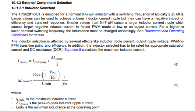
                    in the TPS62811-Q1 datasheet , the range of inductor has been specified and 0.47uH is recommended in the example application circuit. But by taking inductor ripple current as 30% of maximum output current, if I calculate the required output inductor value doesn't match. Is there any specific formula or the output capacitor also considered for the calculation?

Thanks,

Regards,

Roopa.

  • Hello Roopa,

    For calculating the inductor value, only inductor ripple current is not the important parameter to consider. This value is chosen keeping in mind the loop stability in combination with output cap, efficiency and also PFM to PWM transition point etc.

    Thanks,

    Farheen

  • Hello Farheen, thanks for the quick reply.  If I consider the equation 9, with estimated ripple current I am not able the get the 'Inductor Value'. As you mentioned several factors would affect the inductor selection, how do we estimate the inductor for worst case conditions. If you could help me with detailed procedure it would be really helpful.

  • Hello Roopa,

    Let me look at it.  What are your test conditions? Vin, Vout, Load current (Max and Min, Typ), fsw, Imin(assume 10% of Iout)

    Also with this formulae you will be able to get the minimum inductor value. What you are getting? Because you have to consider derating of the inductor, when selecting the inductor value becaus this formulae does not count that.

    Thanks,

    Farheen

  • Hello Farheen,

    Vin----->4.093V, 4.989V,5.051

    Vout----->3.093,3.315,3.547

    Iout---->0.0958A,0.2296A,0.3634A

    Fsw--->1.97, 2.233,2.67 (MHz)

    Also,deadtime, rise time , fall time of the switches, gate drive details are missing in the datasheet, it is difficult to estimate the IC Power dissipation.

    Thanks,

    Regards,Roopa

  • Hi Roopa,

    If I take the Vin_max: 5V, Vout_max 3.5V and fsw=2.233MHz and 30% of Iout (0.5A as max current), I get 3.13uH. Then we have to consider derating of the inductor also and other parameters that I have told you.

    But this equation in the datasheet is to calculate the maximum inductor ripple current, not the inductor value. Because this inductor value is choosen by designer by considering some internal parameters also which makes sure that device runs fine in all conditions.

    More, Webench tool for this device can give you an approximate idea about IC power dissipation. 

    Thanks,

    Farheen

  • Hello Farheen,

                            as you mentioned I have taken all the factors which has been mentioned in the datasheet, going ahead with the fact that low value of inductance and max  value of capacitance for better transient response, values are proper. But my concern is Inductor ripple current with inductor tolerance over the long run ,what impact would it have?

    Thanks,

    Regards,

    Roopa.

  • Hello Roopa,

    As long as effective inductor value is above the minimum limit that is mentioned in the datasheet and inductor saturation current is higher than current limit of the datasheet, it should be fine.

    Thanks,

    Farheen