This thread has been locked.

If you have a related question, please click the "Ask a related question" button in the top right corner. The newly created question will be automatically linked to this question.

UCC28C56H: Output voltage reduces with load

Part Number: UCC28C56H


Hello TI,

We have a custom transformer made and have designed a PCB based on your EVM.

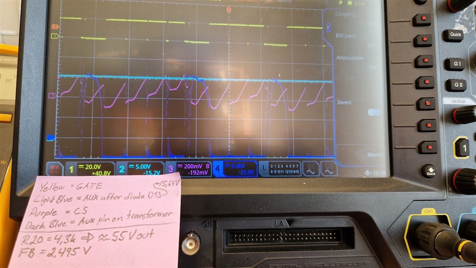
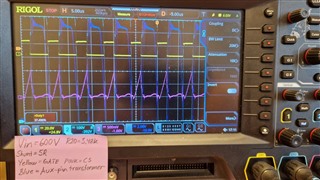
We have set a 55V output but once we load with 47ohms, it goes down to around 45V and at 100ohm load the Vout goes down to 36V. Why is that?

Aux seems to stay the same.

  • We only measured spikes on the mosfet source where it looked <600mV. I just noticed that our Ccs is far from the IC and the spikes have not been measured on the IC side, we do that tomorrow and let you know.

    Otherwise, maybe you have other suggestions where to look at?

  •  Hi Valentinas,

    Thanks for connecting through TI E2E. 45V with 47Ω is ~43W and 36V with 100 Ω is ~13W. Lighter load means more output voltage drop - this doesn't make sense. The original design was only rated for 40W over the wide input range of 125V<VIN<1kV.

    1. Double check your transformer polarity and make sure the PCB connections are correct according to the dot polarity of the Wurth sample.
    2. What is your input voltage range?
    3. What is your expected max output power?
    4. Measure the CS directly at the IC.
    5. You mentioned that you measured 600mV, voltage spikes on the MOSFET source but do you see the CS as a ramp signal?
    6. Is the converter operating in DCM or CCM?
    7. Also measure COMP and FB.
    8. Make your measurements using tip and barrel probing techniques as shown below. Also please download and tray TI Power Stage Designer and make sure your power stage waveforms are reasonable.

    Regards,

    Steve M

  • Hello Steve,

    I want to correct myself about 47Ohm load producing 45V output, i meant 1k load.

    • The transformer polarity is correct.
    • Input voltage range that we want to achieve is 650-900V but for testing purposes we are running up to 200V.
    • It operates in CCM.
    • Max expected output power is 30W
    • We measured CS pin at the IC and its below 600mV.

    We have Vin 120V. R20 we have set to 4.7k and the output voltage is 55V with a 1.3k load. The IC VDD is powered externally by 20V, because our AUX winding ratio is too low, so AUX is disconnected from VDD. By varying the input voltage, the DC is around 75% and changes up and down as expected, but when we increase the load to 100Ohms, the DC decreases to 70% and it outputs 32V. Strangely, the AUX does not reduce, it is always 14.5V.

    Why is the AUX always 14.5V even if the Vout changes? If we change Vout to be different, then AUX does change accordingly, but during output load, the AUX does stay stable while the Vout drops.

    At Vin 120V, COMP is 1.3V. At Vin 40V its 1.46V.

    We tried setting R20 = 4.3k. The duty cycle becomes very high under no load and it consumes around 100mA which heats up the switching components. Seems that it goes into high DC mode because the FB goes <2.5V. (Photo below)

  • Valentinas,

    1. The CS signal is not good - the measurement appears to not be referenced to GND. Is this the measurement taken directly across the CS resistor which is GND referenced? 
    2. The converter appears to be oscillating due to subharmonic oscillation? If you designed the converter for peak CMC with max duty at min input voltage which is supposed to be 650 V but you are testing at 200 V, what is the theoretical duty cycle under this condition? I expect much greater than 45% and this would create the instability you are seeing?
      1. You need to test at the input range the converter/transformer was designed for, 650 V<VIN<900 V
      2. If you look at the main output voltage just before and after it starts to drop, do you see any indication of oscillation?
    3. The aux winding is not dropping out because there is no load on AUX. It is acting as a peak detector so that even though the duty is changing on the main output which is loaded and the main output is being reduced with load, I suspect the AUX output is being held up by whatever capacitance is on AUX. Adding even a small load to the AUX winding should show that it will drop proportionally according to the main output.
    4. Have you tried TI Power Stage Designer to see what the expected waveforms look like under the exact conditions you are testing?

    Steve

  • Hello Steven,

    We have solved this issue, it was due to leading edge blanking not staying long enough, so our CS parasitics have triggered the overcurrent protection. We increased the time constant and now it does not trip overcurrent anymore so the output voltage stays stable during loading.

    FYI increasing Vin to 600V did not do any help.

    Another problem we have is - if we reduce R20 to 3.48V (to output 68V), Vfb does not reach 2.5V so it runs in high duty cycle to try and reach that 2.5V. My understanding is that it does not reach the 2.5V because Vcs reaches 1V and overcurrent triggers which turns off the gate and Vout does not increase anymore.
    It seems to work with R20 = 5.1k which sets around 55V, then Vfb reaches 2.5V and the duty cycle is low as it should.
       

    I think that Rcs needs to be reduced a bit so the Vcs wont reach 1V as fast which means higher higher duty cycle for a short time until the Vout reaches 68V and Vfb reaches 2.5V, then it should into lower duty cycle. Am i correct?

  • Waveforms look much better - sound correct, like you are on the right track. Make sure your max duty cycle is happening at minimum VIN and the CS resistor is sized appropriately so that you don't cross the threshold during normal  operation.

    Regards,

    Steve M