Because of the Thanksgiving holiday in the U.S., TI E2E™ design support forum responses may be delayed from November 25 through December 2. Thank you for your patience.

This thread has been locked.

If you have a related question, please click the "Ask a related question" button in the top right corner. The newly created question will be automatically linked to this question.

TPS65131: R7 / C3 value in heavy load

Part Number: TPS65131
Other Parts Discussed in Thread: LM60430,

Hi Team,

For section 8.2 application information of TPS65131RGER in the datasheet,

The VIN input has R7 (100ohm) and C3 (100nF) (the time constant is 10us),

When I measured in the test, the power supply turned on without load.
When testing with load, the power supply did not start up, so R7 was changed to 100kohm and the time constant was changed to 10ms.
However, the power supply did not start up both with load and without load.
I think it will not start because the time constant is long.

What is the optimal R7 value (time constant) and the maximum value of the time constant?

I understand that R7/C3 should use 100ohm and 100nF.
But when it does not start up under heavy load, start +5V fully and then raise +/-15V.
I try to change the time constant of R7/C3. Is there any other way?

Is there other solution, such as changing the constant of 47uF × 4 of the output capacitor?


Thanks.
Regards,
Frank

  • Hi Frank,

    Could you please share your schematic to me?

    And what do you mean as the "power supply"? Is it the input voltage or the VPOS and VNEG?

    BR

    Patrick

  • Hi Patrick,

    Thank you for your support.

    power supply means input voltage.

    Please find the attached schematic.

    I will send this schematic to your email.

    Input:5V
    Output:+15V、-15V
    Current:+15V→240mA、-15V→90mA
    L1 value:10uH
    L1 part number:SLF7055T100M2R53PF

    Thanks.

    Regards,

    Frank

  • Hi Patrick,

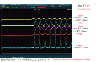
    I have attached the ripple when the power supply is not turned on.
    Can you tell me how to suppress current at startup?

    Tell me if there are any changes to my schematic.

    The customer is in a hurry, can you help me analyze this issue?

    Thanks a lot.

  • Hi Frank,

    1. In the waveform, is the P5V tested directly at the 5V input?

    2. How did customer supplied the input voltage 5V? Is it from another IC or maybe a DC source? If it's from another IC, I'd suggest they try to use a constant DC source for testing. Maybe this issue is caused by the current limit of the front IC.

    BR

    Patrick

  • Hi Patrick,

    1. yes, In the waveform, the P5V is tested directly at the 5V input.

    2. I use TI LM60430 on  24V to 5V power supply, I will send a private message of 5V schematic to you.

    Please let me know the possible cause. 

    Regards,

    Frank

  • Hi Frank,

    I've also sent to you by message.

    Seems LM60430 can only 3A output current, but in the waveform you sent to me, the input current is over 3A. So I think this Vin voltage drop is caused by the LM60430 current limit.

    I'd suggest customer to use a constant 5V DC source with larger current first to see whether the IC can work normally. And to capture the largest value of input current.

    If the IC can work normally with DC source, to continue using LM60430, I think customer can try to add a several nF capacitor between BSW pMOS gate and source to slower the pMOS, which is helpful for reducing start-up inrush current.

    BR

    Patrick

  • Hi Patrick,

    I have observed overcurrent state.
    The LM60430 has a hiccup mode, which enters the hiccup mode when the FB pin input is below 0.4 V.
    Stop switching 94 ms,then soft start.
    If the short circuit condition persists, the device operates at the current limit for 20 ms and then shuts down as shown in the datasheet.

    Due to the large inrush current of +24V, we would like to stagger the start timing of +5V, +15V and -15V.
    How do I adjust the +15V and -15V start timing for the TPS65131?
    We believe that the starting timing can be changed by inserting the resistor and capacitor into the ENP (8-pin) and ENN (10-pin) and the time constant.
    How many time constants would be better to enter?
    Please tell me what is the maximum value of the time constant.
    Thanks.

    Regards,
    Frank

  • Hi Frank,

    For +15V, just as I mentioned previously, you can add a several nF capacitor between BSW pMOS gate and source to slower the pMOS to reduce the +15V inrush current. Also you can use the ENP resistor and capacitor to change the starting time.

    For -15V, I think the resistor in series and capacitor in parallel can be used to control the starting time as well.

    But unfortunately, for now we don't have test data related to these spec so that it's hard to give a solid advice on choosing the components value. This IC has an internal soft-start time as 1ms typical, so it's recommended not to set the starting time longer than this.

    BR

    Patrick