This thread has been locked.

If you have a related question, please click the "Ask a related question" button in the top right corner. The newly created question will be automatically linked to this question.

BQ25700A: Charging Current Oscillation with different brand resistors

Part Number: BQ25700A
Other Parts Discussed in Thread: TPS55288

Hi team,

        Our customers get  interesting trouble in charging oscillation on BQ25700A . They use adapter with 20V 5A  to charge 4s batteries where they set the maximum charging current at 4A.They control the charging current from 0A to 4A.And the sw frequency is 800kHz.

        In their application, there is two brands resistors on the current sense resistor named (R89 CAR1206). They find that when they use current sense resistor from brand A as R89, they test the the oscillation on input current and output current shown in slides. But they use resistor from brand b, in same scenario, they do not find oscillation.

      BQ25700a_0407.pptx

      Could you please answer the questions below:

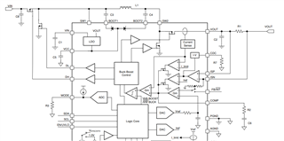
      1.could you please to review the schematic?

      2. Do we have such resistor selection criteria?

      3. do you have any idea about how different resistors causing the oscillation?

      4. Could you please share how the input current  measured by ACN and ACP affect the control loop? I find the TPS55288 which is current-average-mode buck-boost convert. Is the control topology of BQ25700A same as TPS55288?

YOURS

NAN

  • Hello Nan,

    Thanks for working with this part.

    1. Here is our schematic checklist. C50 and C51 are to large for being right after RAC. And, there should be a 33 uF high frequency tantalum cap with the input caps. We also recommend placing a 0.47 uF cap right next to the VBUS pin.

    For the output circuit design, is their a system voltage output or is the circuit only charging a battery?

    You might want to take a look through the checklist yourself. I only got through the first two sections of the schematic checklist.

    2. We don't have a specific selection criteria for the RAC resistor.

    3. Maybe the resistors have different parasitic inductance or parasitic capacitance? Have you found any significant differences between the two datasheets?

    4. I can not share the exact specifics of the control loop. The resistor is used for the INDPM function for the part though.

    Best Regards,
    Ethan Galloway

  • Hi Ethan,

         Thanks for your reply.

         As for Q1, you suggest to use 33uF tantalum cap. The customer want to use the 33uF ceramic capacitor instead of tantalum cap. Could you tell my why you suggest to use tantalum? Is that reasonable to use ceramic capacitor to replace?

    YOURS

    NAN

  • Hello Nan,

    Here's the schematic review for the BQ25700A. I meant to link this to you earlier.

    The review recommends a tantalum capacitor to avoid the DC-Bias effect and to handle the temperature variation effect.

    Please let me know if you have any more questions.

    Best Regards,
    Ethan Galloway