This thread has been locked.

If you have a related question, please click the "Ask a related question" button in the top right corner. The newly created question will be automatically linked to this question.

LM76002: Tying SYNC/MODE pin directly to 5V

Part Number: LM76002

Hi Team,

we have used the LM76002 in several of our designs already and we're very pleased with its performance. We mostly use the converter to create a 5V supply from a 24V input.

Now, I've just stumbled across this thread, which has made us a little insecure about our design:

https://e2e.ti.com/support/power-management-group/power-management/f/power-management-forum/805285/lm76002-mode-pin-pull-up?tisearch=e2e-sitesearch&keymatch=lm76002%25252520mode#

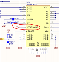
Long story short, we're always using the LM76002 in FPWM mode and we're therefore pulling the SYNC/MODE pin high. Now, as mentioned in the linked thread above, we were also thinking that loading of the VCC pin on the LM76002 is not allowed (as mentioned in the datasheet) and therefore pulled SYNC/MODE high by directly connecting the pin to the 5V output voltage of the buck converter. Do you see any issue with doing that? Since there is no statement about the SYNC/MODE pin voltage range in the "Recommended Operating Conditions" section of the datasheet but only a 5.5V Abs Max Rating, we're a little worried if the pin is intended to be driven by 5V directly.

We would really appreciate it, if you could provide some clarification regarding this topic.

Thanks and best regards,

Sebastian

  • Hello Sebastian,

    The mode/sync pin is high-impedance and takes low current from VCC hence, why it is OK to be driven with it. 

    Do you see any issue with doing that?

    Assuming the absmax is not violated (the 5V is well regulated), I have no concerns with MODE/SYNC being connected to 5V.

  • Thank you for the quick reply.

    It's good to know, that the design will not cause an immediate problem, since the 5V supply is indeed well regulated. We will definitely consider changing the connection to VCC in future designs though, since there will be more margin to abs max.

    From experience, I consider TI's datasheets to be very detailed and clear but in this case I would recommend to clarify this specific topic in future datasheet revisions, since it's not really obvious what the actual impedance of the SYNC/MODE pin is. Maybe the possible connection to VCC could be highlighted in the "Typical Applications" section by adding "GND or VCC" to the SYNC pin in the circuit diagram (just an idea).

    Best regards,

    Sebastian

  • Hello Sebastian, 

    thanks for the advice. I will forward that on to the team.