This thread has been locked.

If you have a related question, please click the "Ask a related question" button in the top right corner. The newly created question will be automatically linked to this question.

UCC28634: DRV will not send any pulse signals

Part Number: UCC28634

I received the design from the TI Webench and laid out the circuit on a PCB. When i built up the board I was not seeing the DRV switching. I troubleshot this for a while and decided to build up a second PCB with minimal components installed. Below is the original design from TI Webench and highlighted parts that were installed on my second PCB. 

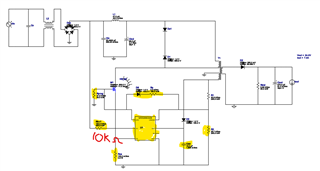
On the second PCB i installed only the low voltage components highlighted above (the HV resistor was changed to a 10k ohm to reduce the need for higher voltage on the PCB to startup) and applied a 16.5VDC voltage to the HV pin (on both either side of the 10k resistor to this pin to see what would happen) and 15V to the VDD. I never saw any pulsing at the DRV pin.

Could you please help me figure out why i was not seeing any lulses at the DRV, including the exploratory pulses?

Thank you,

  • Hello,

    I am reviewing your inquiry and will get back to you shortly.

    Regards,

  • Hello,

    Are you shore you are not seeing a DRV signal?

    When the device first power's up it is going to give 3 gate driver pulses sampling for faults such as input under voltage, output over voltage and over current.

    If it sees any one of these faults it swill cycle VDD between VDDon and VDDoff to reset the fault.

    The following link will bring you to an application note that descries how primary fault sensing works, common issues with it an how to resolve them.  I believe this information will help you troubleshoot your design.

    https://www.ti.com/lit/pdf/sluaac5

    Regards,

  • Mike O'

    Thank you for the response. I was able to figure out why i was not getting a DRV signal. There was a crack in the trace between the pin and the test point i was monitoring. Once i fixed this i was able to get the three exploratory pulses as well as additional startup pulses. The system was able to operate yesterday for about 50ms before a fault would occur and teh system would auto-restart, each time faulting after about 50ms. I am still troubleshooting this issue. If you have any recommendations of what could consistently fault around 50 ms (don't believe its the 40ms UV since the DC link is still well above 100VDC) please let me know. 

    Thank you,

    Doug Hall

  • Mike O',

    Thank you for the response. I was able to figure out the DRV issue. There was a broken trace between the DRV pin and the test point i was monitoring. Once i fixed this issue i was able to see the three exploratory pulses and additional startup pulses, giving me the output voltage i was expecting. However, after ~50ms of switching a fault would occur and the system would shutdown and auto-restart. Do you have any ideas of what would cause the system to fault consistently at 50ms? I don't believe it was the 40ms undervoltage as the DC link was still at >100VDC. I am assuming there is some noise on one of the signals lines but haven't found that out yet and not sure why it would consistently wait 50ms before faulting.

    Thank you,

    Doug Hall

  • Hello,

    I am reviewing your inquiry and will get back to you shortly.

    Regards,

  • Hello,

    The most common issues with primary fault sensing is noise on the aux winding and current sense (CS) pin trigger OVP and OCP faults.  These issues can be resolved by snubber circuits, RCD clamp and filtering.

    The following link will bring you to an application note that descries how primary fault sensing works, common issues with it an how to resolve them.  I believe this information will help you troubleshoot your design.

    https://www.ti.com/lit/pdf/sluaac5

    Regards,