This thread has been locked.

If you have a related question, please click the "Ask a related question" button in the top right corner. The newly created question will be automatically linked to this question.

TPS61161A: SW pin is not generating switching frequency.

Part Number: TPS61161A


Dear Team,

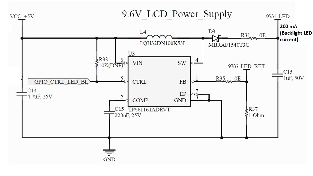
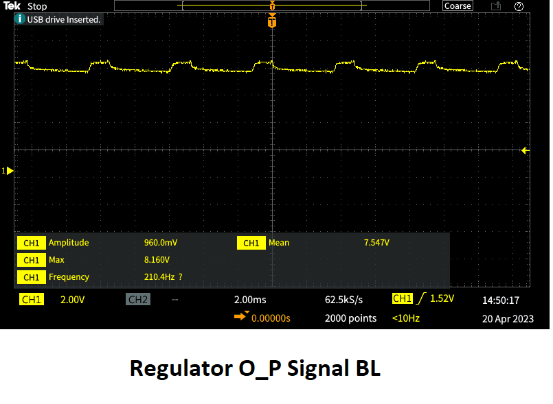
Problem facing: IC is not generating the switching pulse at SW pin even after providing the CTRL pin PWM signal.

 Please provide any solution.

    Input conditions:

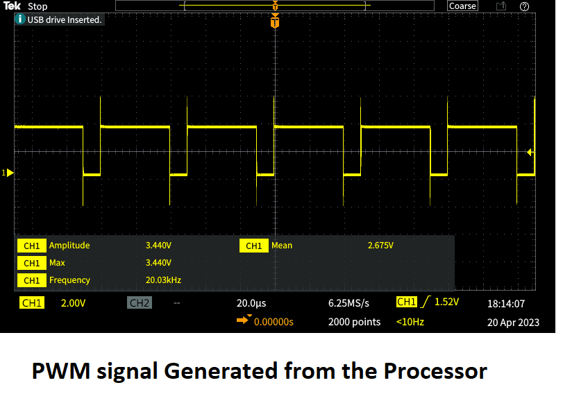
                1) CTRL Pin input frequency 20Khz, 80% duty cycle. with 3.3V level

                2) VCC+5V with 2 Amps capability,

   Circuit Components:

                1)  Input capacitor 4.7uF/25V

                 2)  Inductor 10uH / 450mA

                 3)  MBRAF440T3G DIODE SCHOTTKY 40V 4A

    Backlight LED of Display:

                 1)  3 LED's in series and same pair repeated 10 times in parallel.

                 2) Each LED 3.2V forward drop and total current consumption is 200mA


  • Hi,

    The schematic looks fine from my side. So I think you can capture the waveform at the start up moment to see whether SW has tried to switch or it doesn't switch at all.

    Please also capture COMP and VIN together with SW at the same time.

    BR

    Patrick

  • Hi Patrick,

    Thank you for responding.

    Input voltage condition: 5V 2A

    When display connected to the circuit and PWM is supplies to the IC from processor, the circuit is drawing high current and Display backlight is not getting power on.

    Input voltage condition: 5V 0.5A

    Alternatively, i placed 10k resistor at R33 and captured the signals (Input PWM connection is removed). Still Ic was consuming high current, but it is powering the backlight LED's, i have captured these signals by powering the IC for 5 sec to avoid damage to the circuit.

    Display Back light LEDs are working fine when i am connecting them to the power supply.( to check whether the Backlight LED issue)

    Please find the below signals captured from CRO.

  • Hi,

    1. I would suggest you check the processor which generates the PWM wave. The 2A input current is already over the normal condition.

    2. When you place the R33 and disconnect the PWM, the 0.5A input current is normal I think. Because you set output current as 200mA, so with output voltage ~9.6V and input voltage 5V, the 0.5A input current seems reasonable.

    3. And the inductor saturation current is kind of low as well. Over 0.8A is more recommended.

    4. May I know how many boards have you tested? Could this issue be 100% reproduced with every board?

    BR

    Patrick

  • Hi Patrick,

    1. I reduced the cable length of PWM.

    2. When i placed R33 all displays are running fine now, after changing the Inductor with higher current and placing the external ground cable from the interfacing board to the Carrier board.

    3. Updated

    4. I have placed on 3 different boards and all the 3 PCB's are generating the same issue as given below.

      Current issue is when I am placing R33 Display backlight is working fine, But when i am trying to control with PWM. It is directly shutting down the backlight LED power. I tried with 10Khz and 20Khz with 80% duty cycle.

    Thanks for your reply Patrick.

  • Hi,

    Is the "PWM signal generated from the processor" captured when the PWM connected to CTRL? If not, could you please capture the waveform of PWM when it is connected to CTRL pin?

    When you applying PWM to CTRL, is R33 placed as well or it was removed?

    You can also try to find where the up to 2A input current flowed to.

    BR

    Patrick

  • Hi Patrick,

      As you said i have captured the PWM signal, which is generated from the Processor and attached,

    When i am applying PWM to CTRL pin i am not mounting R33.

    Current issue is:

    When i am connecting the CRO probe to the control pin then IC is providing the SW signal and my LED backlight is working fine,

      if i remove the CRO probe then it is not generating the SW signal.

    Have you faced this issue before and also provide the solution regarding this, 

    What i am suspecting is do i need to have more grounding for IC, or do I need to add any capacitance in between CTRL pin to the ground (Which is offering from CRO probe Capacitance).

  • Hi,

    Could you please try using the signal generator to generate the PWM and to see if this can control the IC normally? I still suspect this issue is caused by the abnormal PWM wave.

    BR

    Patrick

  • Hi Patrick,

      It is working fine now, I placed a Pull-down resistor with 1k ohm, on control pin and it started working with the same PWM from processor, I think PWM signal noise is due to probe length.

    Thank you, Patrick, for giving me a ray of hope.


  • Hi,

    Happy to hear the problem is solved, I'll close this thread now. If you have other questions, please reply to this thread and it will re-open again.

    BR

    Patrick