This thread has been locked.

If you have a related question, please click the "Ask a related question" button in the top right corner. The newly created question will be automatically linked to this question.

LM5146-Q1: The difference of the bode plot generated by the quickstart and webdesigner

Part Number: LM5146-Q1
Other Parts Discussed in Thread: LM5146, CSD17304Q3, CSD17573Q5B, LM5145-Q1, LM25145, LM25148-Q1

Hi team,

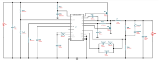
    I am using LM5146 for design, which requires input 12v and output 2v@10A. The reference design obtained by using webdesigner is shown in the following figure(the highside mos is CSD17304Q3,the lowhside mos is CSD17573Q5B):


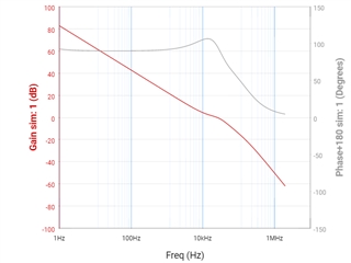
     Through simulation, it is found that the phase margin and gain margin are far beyond the recommended value. Is this normal?


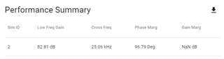
   Also enter the circuit parameters from webdesigner into quickstart, bode plot below:


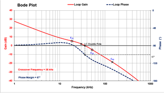
  It can be seen that the phase margin and gain margin calculated by quickstart differ greatly from that of webdesigner. May I ask which design I should use for reference?
Attached is the official quickstart program.

   LM5146-Q1 Quickstart Tool r2 - 12Vin 2Vout 10A 255kHz.xlsm

  • Hello,

    Please use the derated value for Cout (with applied voltage and temperature) to derive the bode plot. This is important as the position of the LC double pole impacts the loop compensation.

    Btw, the values for Cin and Cout seem low here for this 10A 255kHz design. Also, as Vin-max is quite low here, you don't need a 100V controller. Take a look at the LM25145 (42V, not Q grade though) or the LM5145-Q1 (75V). We typically use 42V controllers for 12V automotive inputs - see the LM25148-Q1 for example.

    Regards,

    Tim

  • Hi tim,

      Thank you for your recommendation.

      Actually, my question is which circuit parameters should I design for LM516-Q1? It seems that webdesigner and quickstart are quite different, which makes me confused.

  • Hi Suy,

    The best recommendation is to keep phase margin above 60degrees, and maximize crossover frequency.

    It appears WEBENCH phase margin is 90degrees, which is quite overspeced.

    Your quickstart shows 67 degrees, which seems fine.

    However as Tim mentioned it's important to use de-rated capacitance in the quickstart calculator's output capacitance.

    Hope this helps,

    -Orlando

  • Hi Orlando,

       Thank you for your reply.
    I have increased the value of the output input capacitance, which is another problem. My question is that all parameters in quickstart are parameters given by WEBENCH, and quickstart calculates the phase margin better than WEBENCH. If there is no problem with the calculation method in quickstart, can we say that the bode plot given by WEBENCH is wrong? We hope to get your confirmation.

    Below is a WEBENCH bode plot

  • Hi Suy,

    Your quickstart had upper FB resistor of 10kΩ, however WEBENCH uses 18kΩ.

    When you update the QS to 18kΩ the crossover and phase margin are much closer to WEBENCH.

    (Note the quickstart shows the phase margin of 100 degrees on the phase axis)

    Hope this helps,

    -Orlando

  • Hi Orlando,

    Yes, WEBENCH and QS are very close now, many thanks.
    Let me ask again why WEBENCH has such a set of parameters. After all, the phase margin of this set of parameters is 90db and beyond the design requirements,Are other considerations more important?

  • Hi Suy,

    I'm not sure about the WEBENCH phase margin design process, however with WEBENCH you can optimize for low cost, efficiency, or small solution size.

    These optimization change the output capacitance, and that changes the loop response. 

    I think that's part of the reason.

    Hope this helps,

    -Orlando

  • Hi Orlando,

     I got it. I‘m appreciate your help.