Other Parts Discussed in Thread: TMS570LS1224, BQ79616
Hello
I'm trying to use the BQ79616EVM-021 with the hercules TMS570LS1224, with the exemple provided by texas I was able to read the voltage from the battery.
Now i'm interested in read the adc voltage from the GPIO pin in the BQ79616 board. I'm not sure why i'm not getting the right values.
My code is the modify from the example:
/** @file sys_main.c
* @author Vince Toledo - Texas Instruments Inc.
* @date February 2020
* @version 1.2
* @note Built with CCS for Hercules Version: 8.1.0.00011
* @note Built for TMS570LS1224 (LAUNCH XL2)
* @brief This file contains and calls sample functions for the BQ79616-Q1
*/
/*
* Copyright (C) 2009-2016 Texas Instruments Incorporated - www.ti.com
*
*
* Redistribution and use in source and binary forms, with or without
* modification, are permitted provided that the following conditions
* are met:
*
* Redistributions of source code must retain the above copyright
* notice, this list of conditions and the following disclaimer.
*
* Redistributions in binary form must reproduce the above copyright
* notice, this list of conditions and the following disclaimer in the
* documentation and/or other materials provided with the
* distribution.
*
* Neither the name of Texas Instruments Incorporated nor the names of
* its contributors may be used to endorse or promote products derived
* from this software without specific prior written permission.
*
* THIS SOFTWARE IS PROVIDED BY THE COPYRIGHT HOLDERS AND CONTRIBUTORS
* "AS IS" AND ANY EXPRESS OR IMPLIED WARRANTIES, INCLUDING, BUT NOT
* LIMITED TO, THE IMPLIED WARRANTIES OF MERCHANTABILITY AND FITNESS FOR
* A PARTICULAR PURPOSE ARE DISCLAIMED. IN NO EVENT SHALL THE COPYRIGHT
* OWNER OR CONTRIBUTORS BE LIABLE FOR ANY DIRECT, INDIRECT, INCIDENTAL,
* SPECIAL, EXEMPLARY, OR CONSEQUENTIAL DAMAGES (INCLUDING, BUT NOT
* LIMITED TO, PROCUREMENT OF SUBSTITUTE GOODS OR SERVICES; LOSS OF USE,
* DATA, OR PROFITS; OR BUSINESS INTERRUPTION) HOWEVER CAUSED AND ON ANY
* THEORY OF LIABILITY, WHETHER IN CONTRACT, STRICT LIABILITY, OR TORT
* (INCLUDING NEGLIGENCE OR OTHERWISE) ARISING IN ANY WAY OUT OF THE USE
* OF THIS SOFTWARE, EVEN IF ADVISED OF THE POSSIBILITY OF SUCH DAMAGE.
*
*/
/* USER CODE BEGIN (0) */
/*
* A0 SILICON - CONNECTIONS BETWEEN BQ79616EVM AND LAUNCH XL2 (TMS570LS1224)::
* bq79616EVM J3 pin 1 (GND) -> LAUNCH XL2 J3 pin 2 (GND)
* bq79616EVM J3 pin 2 (NFAULT) -> LAUNCH XL2 J4 pin 10 (PA0)
* bq79616EVM J3 pin 3 (NC) -> FLOAT
* bq79616EVM J3 pin 4 (RX) -> LAUNCH XL2 J2 pin 4 (UATX)
* bq79616EVM J3 pin 5 (TX) -> LAUNCH XL2 J2 pin 3 (UARX)
* bq79616EVM J3 pin 6 (NC) -> FLOAT
* B0 SILICON - CONNECTIONS BETWEEN BQ79616EVM AND LAUNCH XL2 (TMS570LS1224)::
* bq79616EVM J17 pin 1 (NC) -> FLOAT
* bq79616EVM J17 pin 2 (NC) -> FLOAT
* bq79616EVM J17 pin 3 (NFAULT) -> LAUNCH XL2 J4 pin 10 (PA0)
* bq79616EVM J17 pin 4 (NC) -> FLOAT
* bq79616EVM J17 pin 5 (GND) -> LAUNCH XL2 J3 pin 2 (GND)
* bq79616EVM J17 pin 6 (3V3) -> LAUNCH XL2 J2 pin 1 (3V3)
* bq79616EVM J17 pin 7 (RX) -> LAUNCH XL2 J2 pin 4 (UATX)
* bq79616EVM J17 pin 8 (TX) -> LAUNCH XL2 J2 pin 3 (UARX)
* bq79616EVM J17 pin 9 (NC) -> FLOAT
* bq79616EVM J17 pin 10 (NC) -> FLOAT
*
* RELEVANT FILES:
* bq79616.h must change TOTALBOARDS and MAXBYTES here for code to function
* bq79616.c contains all relevant functions used in the sample code
* A0_reg.h A0 silicon revision register map (choose only one register map in bq79616.h)
* B0_reg.h B0 silicon revision register map
* notification.c sets UART_RX_RDY and RTI_TIMEOUT when their respective interrupts happen
* .dil/.hcg used for generating the basic TMS570LS1224 code files, can be used to make changes to the microcontroller
*/
/* USER CODE END */
/* Include Files */
#include "sys_common.h"
/* USER CODE BEGIN (1) */
#include "bq79616.h"
#include "system.h"
#include "gio.h"
#include "sci.h"
#include "rti.h"
#include "sys_vim.h"
#include <math.h>
#include <stdio.h>
/* USER CODE END */
/** @fn void main(void)
* @brief Application main function
* @note This function is empty by default.
*
* This function is called after startup.
* The user can use this function to implement the application.
*/
/* USER CODE BEGIN (2) */
int UART_RX_RDY = 0;
int RTI_TIMEOUT = 0;
BYTE response_frame[(16*2+6)*TOTALBOARDS]; //hold all 16 vcell*_hi/lo values
BYTE response_frame1[(8*2+6)*TOTALBOARDS]; //hold all 8 gpio*_hi/lo values
/* USER CODE END */
int main(void)
{
/* USER CODE BEGIN (3) */
//***********************************************************************************************
//NOTE: CHANGE TOTALBOARDS VARIABLE IN "bq79616.h" to match the number of boards in your system
//***********************************************************************************************
//INITIALIZE TMS570LS1224
systemInit();
gioInit();
sciInit();
rtiInit();
sciSetBaudrate(sciREG, 1000000);
vimInit();
_enable_IRQ();
//INITIALIZE BQ79616-Q1
//need 2 wakes as this particular microcontroller outputs RX=0 by default, and so puts devices into hardware reset while the program is being loaded
Wake79616();
delayms(12*TOTALBOARDS); //wake tone duration is ~1.6ms per board + 10ms per board for each device to wake up from shutdown = 11.6ms per 616 board (rounded to 12ms since variable used is an integer)
Wake79616();
delayms(12*TOTALBOARDS); //wake tone duration is ~1.6ms per board + 10ms per board for each device to wake up from shutdown = 11.6ms per 616 board (rounded to 12ms since variable used is an integer)
AutoAddress();
delayus(4000); //4ms total required after shutdown to wake transition for AFE settling time, this is for top device only
WriteReg(0, FAULT_MSK2, 0x40, 1, FRMWRT_ALL_W); //MASK CUST_CRC SO CONFIG CHANGES DON'T FLAG A FAULT
ResetAllFaults(0, FRMWRT_ALL_W); //CLEAR ALL FAULTS
//VARIABLES
int i = 0;
int currentBoard = 0;
//ARRAYS (MUST place out of loop so not re-allocated every iteration)
// BYTE response_frame[(16*2+6)*TOTALBOARDS]; //hold all 16 vcell*_hi/lo values
// BYTE response_frame1[(16*2+6)*TOTALBOARDS]; //hold all 8 gpio*_hi/lo values
//OPTIONAL EXAMPLE FUNCTIONS
//RunCB();
//ReverseAddressing();
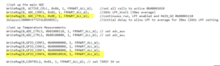
//set up the main ADC
WriteReg(0, ACTIVE_CELL, 0x0A, 1, FRMWRT_ALL_W); //set all cells to active 0b00001010
WriteReg(0, ADC_CONF1, 0x02, 1, FRMWRT_ALL_W); //26Hz LPF_Vcell (38ms average)
WriteReg(0, ADC_CTRL1, 0x0E, 1, FRMWRT_ALL_W); //continuous run, LPF enabled and MAIN_GO 0b00001110
delayus(38000+5*TOTALBOARDS); //initial delay to allow LPF to average for 38ms (26Hz LPF setting used)
//set up Temperature Measurements
WriteReg(0,ADC_CTRL3, 0b01000110, 1, FRMWRT_ALL_W); // set adc_aux
WriteReg(0,ADC_CTRL2, 0b00100000, 1, FRMWRT_ALL_W); // set adc_aux
WriteReg(0,GPIO_CONF1, 0b00000000, 1, FRMWRT_ALL_W);
WriteReg(0,GPIO_CONF2, 0b00000000, 1, FRMWRT_ALL_W);
WriteReg(0,GPIO_CONF3, 0b00000000, 1, FRMWRT_ALL_W);
WriteReg(0,GPIO_CONF4, 0b00010010, 1, FRMWRT_ALL_W);
WriteReg(0,CONTROL2, 0x01, 1, FRMWRT_ALL_W); // set TSREF 5V on
//**********
//MAIN LOOP
//**********
do
{
//*******************
//READ CELL VOLTAGES
//*******************
//reset variables
i = 0;
currentBoard = 0;
//clear out the array so we know we have fresh data every loop
memset(response_frame,0,sizeof(response_frame));
memset(response_frame1,0,sizeof(response_frame1));
//wait single round robin cycle time + reclocking delay for each device, every loop
delayus(192+5*TOTALBOARDS);
//read all the values (HI/LO for each cell = 32 total)
ReadReg(0, VCELL16_HI, response_frame, 16*2, 0, FRMWRT_ALL_R);
/*
* ***********************************************
* NOTE: SOME COMPUTERS HAVE ISSUES TRANSMITTING
* A LARGE AMOUNT OF DATA VIA PRINTF STATEMENTS.
* THE FOLLOWING PRINTOUT OF THE RESPONSE DATA
* IS NOT GUARANTEED TO WORK ON ALL SYSTEMS.
* ***********************************************
*/
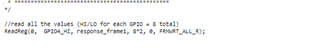
//read all the values (HI/LO for each GPIO = 8 total)
ReadReg(0, AUX_CELL_HI, response_frame1, 8*2, 0, FRMWRT_ALL_R);
//format and print the resultant response frame
printf("\n"); //start with a newline to add some extra spacing between loop
for(currentBoard=0; currentBoard<TOTALBOARDS; currentBoard++)
{
//response frame actually starts with top of stack, so currentBoard is actually inverted from what it should be
printf("BOARD %d:\t",TOTALBOARDS-currentBoard);
/*
//go through each byte in the current board (32 bytes = 16 cells * 2 bytes each)
for(i=0; i<32; i+=2)
{
//each board responds with 32 data bytes + 6 header bytes
//so need to find the start of each board by doing that * currentBoard
int boardByteStart = (16*2+6)*currentBoard;
//convert the two individual bytes of each cell into a single 16 bit data item (by bit shifting)
uint16 rawData = (response_frame[boardByteStart+i+4] << 8) | response_frame[boardByteStart+i+5];
//cast as a signed 16 bit data item, and multiply by 190.73uV to get an actual voltage
float cellVoltage = ((int16_t)rawData)*0.00019073;
//print the voltages - it is (32-i)/2 because cells start from 16 down to 1
//and there are 2 bytes per cell (i value is twice the cell number)
printf("Cell %d = %f\t", (32-i)/2, cellVoltage);
}
printf("\n"); //newline per board
*/
// Temperature display
for(i=0; i<16; i+=2)
{
//each board responds with 32 data bytes + 6 header bytes
//so need to find the start of each board by doing that * currentBoard
int boardByteStart = (8*2+6)*currentBoard;
//convert the two individual bytes of each cell into a single 16 bit data item (by bit shifting)
uint16 rawData = (response_frame1[boardByteStart+i+0] << 8) | response_frame1[boardByteStart+i+1];
//cast as a signed 16 bit data item, and multiply by 190.73uV to get an actual voltage
float Temperature = ((int16_t)rawData)*0.00019073;
//print the voltages - it is (32-i)/2 because cells start from 16 down to 1
//and there are 2 bytes per cell (i value is twice the cell number)
printf("Temperature %d = %f\t", (16-i)/2, Temperature);
}
}
//**********************
//END READ CELL VOLTAGES
//**********************
}while(1);
//**************
//END MAIN LOOP
//**************
/* USER CODE END */
return 0;
}
/* USER CODE BEGIN (4) */
/* USER CODE END */
Is the register setup right?
Where can I found an example?
Thank you