


Hello,
I wanted to attach a file to help calculate the minimum drive current needed for Half-Bridge gate drivers:
Half Bridge Minimum Drive Current Calculator.xlsx
This file will allow users to input their circuit parameters and datasheet values to determine the necessary drive current. The minimum drive current can be used to help evaluate which half-bridge gate driver will be acceptable for the application.
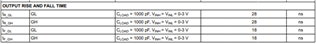
For example, let's assume a Synchronous Buck Converter design running off of a 12V power supply. I want to apply a gate voltage output of 5V, so I would input 5V as my desired Vgs. CSD87588N is an integrated MOSFET solution optimized for synchronous buck operation. The electrical characteristics section of the datasheet will offer a max Qg rating for a specific Vgs, but most datasheets should also include a curve of Vgs and Qg:
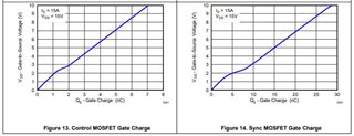
Using these curves, I can estimate a Qg of ~15nC at Vgs = 5V, but I will assume a worst-case max Qg of 20nC to leave some margin. Both the high-side and low-side driver will be only be driving one FET, so the Qg total is equal to 20nC. Lastly, we can view LM2105's datasheet to find typical rise/fall times:
From this information I will plan to use a rise/fall time of 30ns. With all of the circuit information entered, we can now calculate the minimum average drive current needed for the system:
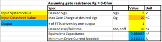
As you can see, the minimum drive current is well within the specs of LM2105 (0.5A/0.8A). Please use this calculator to help determine the minimum drive current needed for your application!
Best,
Alex Weaver