This thread has been locked.

If you have a related question, please click the "Ask a related question" button in the top right corner. The newly created question will be automatically linked to this question.

BQ25798EVM: BQ25798EVM

Part Number: BQ25798EVM
Other Parts Discussed in Thread: BQ25798, USB2ANY, BQSTUDIO

Greetings,

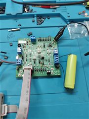
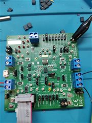
 We want to use BQ25798 in our charger using solar panels. We have got the BQ25798 eval board with us to test the IC. 

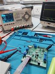
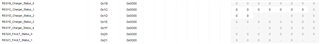
But We are not able to charge the battery, IBus and IBat currents are both 0 mA. It is not consuming anything from power supply as well as ADC value shown are 0.

All the reg parameters looks good and CE pin is also pulled down.

I have tried this with 1S, 2S battery config, same issue is there.

  • Hi Chaitanya,

    Have you tried the recommended test setup and jumper configuration in EVM user's guide at https://www.ti.com/lit/pdf/sluucb5?  Are you attached a simulated battery or real battery with thermistor?  If real battery with thermsitor, the EVM jumper that installs a 10k ohm resistor to simulate a thermistor must be removed.  What is the STAT LED reporting (on, flashing or off)?  What do the I2C status and fault registers per either BQSTUDIO or USB2ANY report?

    Regards,
    Jeff

  • Hi Jeff,

    Thank you for the quick reply.

    1. Yes I have followed the jumper configuration

    2. I have tried both simulated battery and a real battery.

    3. I am not using a thermistor. So I have not removed the 10K Ohm resistor. The jumper is set at Normal config

    4. Stat LED is off.

    5. Both the fault registers are showing no error i.e. REG20= 0x00 and REG21=0x00. All the I2C interrup flags are also LOW. I am using USB2ANY on TI_Charger Web GUI.

  • Hi Chaitanya,

    When you apply power, is that voltage at PMID?  Is there a squarish waveform at SW1 or SW2?  What are the voltages at SYS and BAT?  Can you upload a picture of your test setup?

    Regards,

    Jeff

  • Hi Jeff,

    Yes, Voltage at PMID is same as that of power supply which is 5V

    Voltages at SYS and BAT are 3.3V and 0 V respectively. When battery is not connected.

    Yes there is a Squarish waveform at SW1 and SW2 attaching the pictures.

  • Hi Chaitanya,

    The jumpers are configured for to charge a 1S battery.  The squarish waveform should go from zero to the input voltage (5.0V) you supplied.  The voltage on SYS should be 3.6V at a minimum and then follow the battery up to 4.2V. Is you input source current limit high enough?  BTW, the status and fault registers are from REG0x1B to REG0x27.  What do all of those register report?  Lastly, if you connect to VAC1 instead of the VAC2, any change in operation?

    Regards,

    Jeff

  • Hi Jeff,

    Yes, In above setup jumpers are configured to charge  a 1S Battery. The squarish waveform is not going up to 5V. It is less than 1V. 

    For all the Battery jumper config I am getting 3.3V at SYS and Bat. 

    Here is a screenshot of status and fault registers on TI Charger GUI Website. All of them are reporting 0.

    There is no change in output even if it is connected to VAC1. I have also tried skipping the FETs of VACs, still no change in output.

  • Hi Chaitanya,

    If you remove both input power and the battery, then reattach on the battery and remove the /CE pin jumper (JP17), does the SW waveform look correct? \

    Regards,

    Jeff

  • Hi Jeff,

    We followed your instrunctions, still the waveform doesnt look correct. 

    What do you think is the error here? If we buy a new board, will that help us to evaluate the board faster, Parallely we can debug this one.

  • Hi Chaitanya,

    The IC must be damaged.  I have heard of damage from ringing above/below abs max voltage due to hot plugging >15V adapter at VBUS or fully charged 4S battery at BAT or attaching a battery backwards.   I recommend buying a new board.

    Regards,

    Jeff

  • Hi Jeff,

    Thanks for the confirmation. Please let me know any other precautions to use the board