Other Parts Discussed in Thread: BQ25713, BQ25723, CSD17308Q3, CSD17578Q3A, , CSD18543Q3A
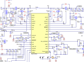
Initially the power bank design was using the bq25713EVM circuitry . Since the bq25713 was unavailable, the bq25723 IC was dropped into the bq25713EVM (tidrxq7) reference design.
For the bq25713EVM, the switching MOSFETs Q1, Q2, Q3, and Q4 are listed as CSD17308Q3. The Vgs (Threshold) is listed at 1.3V.
(For the bq25723EVM, the switching MOSFETs Q1, Q2, Q3, and Q4 are listed as CSD17578Q3A. The Vgs (Threshold) is listed at 1.5V.)
Using a single Li-ion cell configuration, with Vbus = 20V, with charging the single cell, and then discharging at Vbus =20V, Q1 failures occurred for 3/10 units. Replacing MOSFETs and cycling the failed units did not incur additional failures. However, subsequent builds (15 units per build) produced 4 to 5 MOSFET (Q1) failures. The failures occurred at the end of charging and the start of discharging (cell voltage = 4.2V, Vout=20V).
The MOSFET failures display low impedance.
Scope shots display a peak voltage of 29V at the drain of Q1.
Replacing the failed MOSFETs seemed to work but the reworked units seemed to fail at the same rate (30%).
For a quick fix, a new MOSFET, CSD18543Q3A , was substituted for Q1, Q2, Q3, and Q4. However, there is an issue with the power bank discharging in a single Li-ion cell configuration.
The battery can discharge starting from a fully charged state down to a completely discharged state (2.8V).
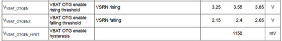
However, if discharging is started at a cell voltage lower than 3.7V, the discharge is unable to start (cell voltage < 3.7V, Vbus =5V).
The circuit is using the bq27513EVM circuit for driving Q2 on (REGN voltage driving Q2 gate high via an NPN with a Schottky turning off Q2 gate).
If the NPN and Schottky are removed and replaced with a jumper directly connecting Q2 gate to LODRIV1 (Pin 29 of bq25723), the limit is decreased to 3.4V.
Under 3.4V, the battery is unable to start discharging.
Replacing Q2 only with CSD17308Q3, the unit is able to discharge starting at any cell voltage (even down to 2.8V).
Two main questions:
1. What was the possible reason for the original MOSFET failure?
2. What was misunderstood with the IC driving voltage and the replacement MOSFET Vgs threshold ?