This thread has been locked.

If you have a related question, please click the "Ask a related question" button in the top right corner. The newly created question will be automatically linked to this question.

UCC28951: UCC28951 Current sense

Part Number: UCC28951

Hello,

I am designing a 2.4 kW PSFB DC-DC Converter. I am using UCC28951. I have used the excel tool provided during my power stage design, and I also used the values of the compensation network from there. I have attached the excel file that contains all my specs.

I am having a difficulty making the converter stable. I see a lot of noise on my current sense signal even though I have a low-pass filter in there. I am unable to exceed 10 A on the output without having stability issues. Also the same at no load. The problem becomes more pronounced, the more the input voltage is increased.

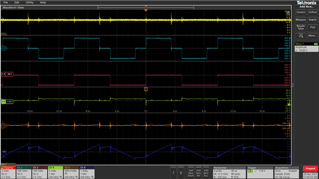
These are my measurements. 

Yellow : Output voltage

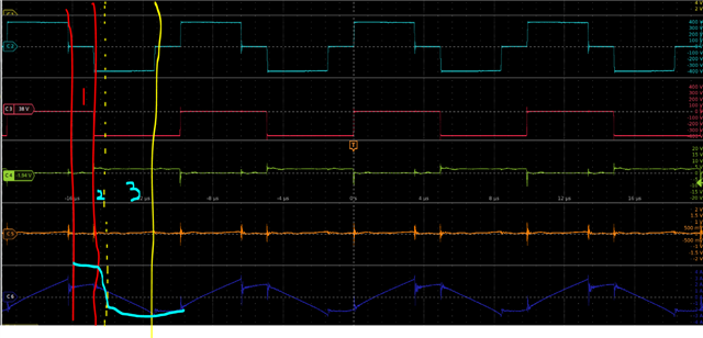
Light blue : Voltage on the primary side of the transformer

Red : Drain-Source voltage of one of the switches

Green : Gate-source voltage

Yellow : Current sense pin

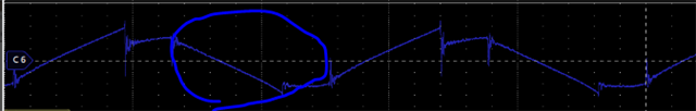
Dark blue: Current in the primary side of the transformer.

 Excel tool.xls

  • Hello Ahmed, 

    Thank you for your interest in the UCC28951 PSFB controller.

    Your question has been directed to an expert on the UCC28951 but due to time proximity to the U.S. weekend, you may not receive a reply until next week.

    Regards,
    Ulrich

  • Hi Ahmed,

    Thank you for the query on UCC28951.

    From your calculations, I see that the only issue is you are using an undersized output capacitor of 1320uF as against the recommended value of 3400uF.

    The turns ratio might require some adjustment as it seems to violate duty ratio limit at minimum input voltage.

    From the waveform below, it seems the slope of the input current waveform looks different with its slow transitions. We need to checkOUTC and OUTD signals along with the CS pin signal. The programmed delays need to be verified.

    Are you using DC blocking capacitor? If it is there please remove this.

    Please also check the SS pin along with the CS signal to see if signal has reached ILIM limit.

    Regards,

    Harish

  • Hello Harish,

    Thanks for your reply and inputs.

    Regarding the output capacitor, I am using it for a battery charging application, that's why I chose a lower value.

    Regarding the minimum turns ratio, I checked at 300 V and it wasn't an issue. The unstability problem happens at higher voltages. The more the input voltage is increased, the more the issue is pronounced.

    I checked the programmed delays, and they are correct.

    I am not using a DC-blocking cap since I am using peak current mode control.

    I increase the voltage from 0 to 400 V. The converter starts regulation at around 300 V. If there is no load the converter will become unstable at around 350 V. If there is a load (10 A), I can reach 400 V, but when I try to increase the load more, the converter becomes unstable.

    Is there a way to check if the problem is mainly from the compensation network, or if it is from another source?

    Kind regards

    Ahmed

  • Hi Ahmed,

    Thank you for the reply and clearing the concerns on the capacitor and turns ratio. That should be ok for now.

    But I am still not convinced about the delays or the PWM switching sense as I feel it could be affected by noise on CS signal. The figure below shows regions 1,2 & 3. In region 2 we expect a sharp transiion in the inductor current due to turning ON of OUTB after dead time (with B & C ON) after region 2. Also region 1 where two of the bottom or top switches are ON, we expect the slope of the transformer current to have a decreasing one if not atleast constant. This is what leads to suspect the transformer current waveform. I would suggest probing all gate signals along with CS and transformer primary current waveform (ensure OUTA-OUTD signals are as per datasheet). Secondly, please try running with diode rectification on secondary by keeping OUTE/OUTF open for now. 

    Please let us know your observations.

    Regards,

    Harish