Because of the holidays, TI E2E™ design support forum responses will be delayed from Dec. 25 through Jan. 2. Thank you for your patience.

This thread has been locked.

If you have a related question, please click the "Ask a related question" button in the top right corner. The newly created question will be automatically linked to this question.

TPS565242: Design help, Excessive Ripple

Part Number: TPS565242
Other Parts Discussed in Thread: ALLIGATOR, TPS565247

Hi, I am attempting to use the TPS565242 to buck from a 12V battery to 5V but experience excessive ripple and noise.

I was wondering if anyone could help me with removing ripple to within 5% at least?

I made a small design on a PCB to test based off the WEBENCH designer which simulates about 12mV of ripple.

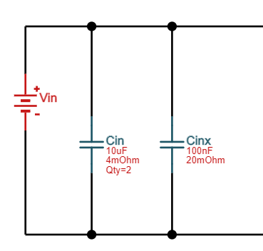
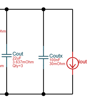
Circuit diagram:

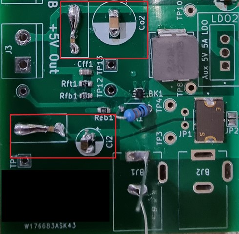
PCB:
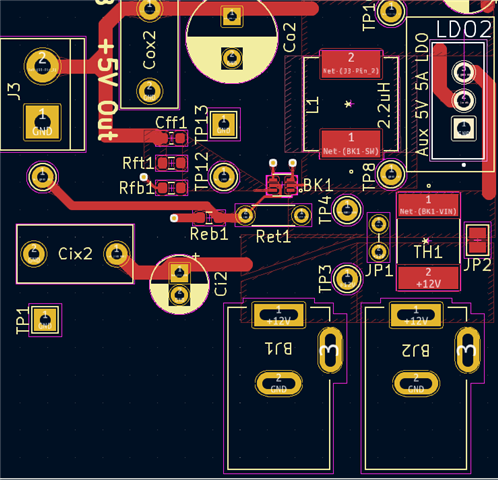
I tested the design with a DC lab power supply providing 12V and checked the 5V output with a multimeter.

The multimeter reads ~5.1V but checking with an oscilliscope shows significant ripple and noise.

I attempted to use a few variations of a capacitance multiplier with a LPF RC circuit on a breadboard with some parts I had around but always dropped too much voltage, as I want a 5V output power rail.

The output after the capacitance multiplier to reduce ripple tended to give me close to 3V of power.

I tested with a N MOSFET and NPN BJTs and also tested a Darlington pair.

Any help or feedback would be greatly appreciated.

Apologies if I missed something, it's my first major design on a PCB and my electrical engineering may be a little rough.

Thank you!

  • Hi Mark,

    Do you simulate the same circuit on Webench as you post in thread? Could you please show your simulation result in Webench?

    As check with layout, 100uF electrolytic capacitor could have high ESR, leading to undesired high output voltage ripple. Please use MLCC to try whether output voltage ripple is still be high.

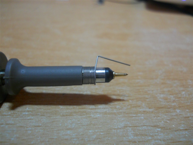
    Another thing needed to be paid attention is measuring method. Please use pig tail to measure output voltage ripple, otherwise the ground wire of probe could import noise and result in high measured Vout ripple. The pig tail installed on probe is shown below:

    My colleague is on leave and he will give you feedback once he comes back to office.

    BRs

    Zixu

  • Hi Mark!

    You can have try with 3.3uH inductor, 4*22uF 10V 0805 MLCC, and 40pF Cff.

    Shuai

  • Thanks Zixu.
    I am getting some MLC capacitors and will test my design again with those instead of electrolytics.
    I was using electrolytics as I had some on hand already.

    I have an alligator clip oscilloscope probe but I will test with a pig tail as well when I get the MLCCs installed.

    I have also gone back to the WEBENCH designer and adjusted to the same parts I have as closely as possible.

    Result:

    It appears that it should work within spec.

  • Thanks Shuai.

    I don't have those parts and would need to prototype another pcb to fit those.

    Is there a benefit to a higher inductor and Cff?

    Is there also a benefit to multiple capacitors to provide similar capacitance levels?

    With WEBENCH, the initial design that it provides uses 2 capacitors for Cin, whereas I elected to replace them with just 1 22uF capacitor.

    The WEBENCH design also has theis for Cout with 3*22uF capacitors which I replace with a single 100uF capacitor.

  • What is the value of ESR of your 100uF cap?

  • I don't have a way to measure the ESR of my capacitors at the moment.

    I originally had electrolytics in for my 100uF, 100nF and 22uF capacitors.

    I modified my prototype board to accept the MLC capacitors I just bought to replace them as recommended by Zixu.

    It's not ideal but using MLC capacitors vastly improved the ripple and noise.

    It is significantly better than before with approximately 15% ripple @ 76mV.

    The 100 uF capacitor used here is a Samsung Electro-Mechanics CL31A107MQHNNWE with some ESR information available here: CL31A107MQHNNN# | MLCC | Product Search (samsungsem.com)

    Not sure which value of ESR I should take note of?

    Other than a new PCB for better capacitor soldering and position on my PCB, is there anything else I should do to improve the ripple on the output?

  • Hi Mark!

    Increase inductor value also can improve the ripple performance.

    Do you the light-load efficiency requirement? If the light-load efficiency is not important in your side, it suggests to use TPS565247.

    Actually, TPS565242 has a better efficiency but its light-load ripple performance is bad. TPS565247(P2P with TPS565242) has very good ripple performance but light-load performance is bad.

    Shuai

  • I'm happy to test a few other inductors such as 3.3, 4.7 and 5.6uH.
    Would you have a particular inductance to recommend and are there any particular parameters I should be aware of other than their inductance?
    e.g. Maximum DC Current/Resistance

    Would you know what the difference at light load efficiency is between the TPS565247 and TPS565242?
    They have the same pinout I believe so I'm happy to buy some and test.
    I think the TPS565247 will be a better fit for my use case with lower ripple in any case.

    I am also awaiting some power resistors to get a better range of loads to test around so that should give me a more comprehensive overview.
    Is there also a better way to test efficiency beyond just power in and out on a load for this?

  • Hi Mark!

    I suggest you directly buy some TPS565247 for test, because the frequency of TPS565247 is fixed 600KHz. We have bench data that with 4.7uH, 2*22uF, ripple can be about 20mV.

    But for TPS565242, the frequency will drop lower. 

    Below the efficiency comparison in datasheet.

    ...