This thread has been locked.

If you have a related question, please click the "Ask a related question" button in the top right corner. The newly created question will be automatically linked to this question.

BQ24170: Battery Charger 3-Cell with single cell auxiliary tap (Recharge issue)

Part Number: BQ24170
Other Parts Discussed in Thread: BQ24172, BQ77915

Hi Ti team,


Hopefully a simple one, regarding the BQ24170 battery Charger IC.


We have designed the BQ24170 set for a 3-Cell (Series) Charger at 12.6V using 18650 3000mAh Cells.


We also have a tap off of the lowest cell in the string to create an Auxiliary 3.3V supply (powering a signal relay), which has a current draw of 65mA.


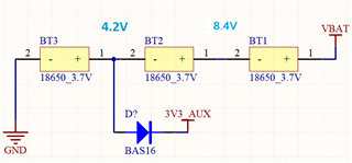
The lowest cell will continue to discharge, powering the signal relay after a full charge cycle.


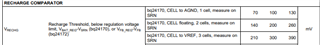
Theoretically, we expect the charger to restart once the voltage dips below a threshold.


What we are experiencing is the charger does not re-attempt a Recharge cycle and goes into a FAULT state anywhere between 1-2 days after power up.


The new good cells all sit at ~ 3.7V/cell before power up. After the FAULT state occurs, the cells out of the circuit measure anywhere from 0V (open-circuit), <1V, or as high as 4.6V/cell.


Additional note we are also using the BQ24170 on multiple products with no issues, no FAULTS, and all Recharging cycles are okay, only difference on this product is the 3.3V AUX tap from the lowest cell in the string.


In theory, we expect a recharge cycle to attempt periodically, if we could have some clarification around the fault/issue that would be great.


Look forward to hearing back.


Kind regards,


Daniel

  • Hi Daniel,

    I haven't seen this before. The charger tries to regulate the voltage sensed at SRN.  For the fully discharged case, I suspect the charger can't terminate, and therefore recharge, either because the charge current never gets below ITERM due to the 65mA or the voltage drop across the top 2 cells.  For 4.6V/cell case, I am assuming these are bare cells without a protector.  If so, then perhaps the bottom cell is not charging and the other 2 cells are over charging?  We don't recommend charging bare cells without a protector.  And that 65mA will prevent the bottom cell charging/discharging in a balanced manner compared to the other 2 cells. It will likely age faster.

    Regards,

    Jeff

  • Hi Jeff,

    Thank you very much, very helpful information we will take into consideration.

    So in our case the charger does complete a charge cycle up to 12.6V and STAT pin indicates charge complete and terminates.

    Its only after sitting their powered from the adapter, that the battery goes into FAULT state after some period of time, <48hrs.

    Could you help confirm what defines the Internal Recharge Threshold voltage that would trigger a new charge cycle?

    As the presumption when we designed the auxiliary tap off of the bottom cell was that the charger would see a small dip in voltage across all 3 series cells and re-start the recharge cycle topping up the slightly depleted bottom cell.

    What we see instead is our bottom cell is completely discharging beyond 2V and damaging the cell due to that 65mA relay load and the recharge threshold is not being met prior to this happening. 

    Kind Regards,

    Daniel

  • Hi Daniel,

    The recharge threshold voltage is shown below:

    I am not surprised that the bottom cell is the only one discharging.  I suspect that sometimes the charger is charging, more less correctly, and the other cells are "picking up the slack" of the bottom cell, hence the 4.6V per cell.  But eventually, once the bottom cell discharges too much, I suspect the charger's battery detection as explained in section 9.3.15 mistakenly thinks no battery is present.

    BTW, it appears you are charging bare cells with a pack protector.  That is not recommended.

    Regards,

    Jeff

  • Hi Jeff,

    Thanks for confirming! We will consider a protector also; did you have a recommendation from Ti?

    I also wanted to check with you; our CELL pin is not referenced to VREF 3.3V as a pullup.

    We had designed in the FB resistor divider for the BQ24172 variant as an option, so for us when using the BQ24170, we have tuned the divider to sit at ~3-4.2V at the CELL pin. Is this going to contribute to any issues with the recharge comparator?

    Kind Regards,

    Daniel

  • Hi Daniel,

    BQ77915 provides celling balancing and protection.  

    CELLS voltage pull up should be okay as long as it stays above 2.5V.

    Regards,

    Jeff

  • Hi Jeff,

    Thanks very much for confirming, we will look at the BQ77915.

    Regards,

    Daniel