First of all, I would like to explain the structure we use.
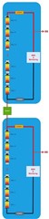
We are using BQ79718. Our battery module consists of 16 cells. Each cell is connected in series with BUSBAR. BMS is fed with BUSBAR from the negative terminal of Cell 1 and the positive terminal of Cell 16. I want to measure the voltage drop across this BUSBAR (Cell 16 positive terminal). I wanted to see this with BB pin on BQ79718.
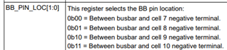
When I examine the datasheet there are limited locations for the BB pin. You can observe this in the BB_PIN_LOC registry below. My question here is BB pin 16. Can I connect it to the positive terminal of the cell? If this is the case, what should my hardware configuration be?
How else can I find a solution if I cannot use the BB pin in the structure I want. What is the BB pin used for? What is its purpose? Why is there a position limitation?
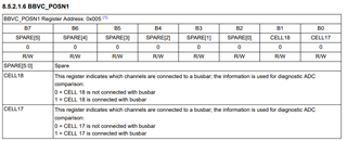
As seen in the picture below, what are the BBVC_POSN1, BBVC_POSN2 and BBVC_POSN3 registers used for? I didn't fully understand this. Our 16 cells are connected in series with small BUSBARs. How should I configure these registers for this?
I tried to explain the structure of our system in the picture below. I supply power to the board with BUSBAR from the positive terminal of Cell 16. Here, contact resistance, BUSBAR resistance, temperature etc. there is a voltage drop for some reason.
So I ask you to pay attention to the BB pin position.
Waiting for your information sharing and solution suggestions.