This thread has been locked.

If you have a related question, please click the "Ask a related question" button in the top right corner. The newly created question will be automatically linked to this question.

LM5100B: LM5100B - Source/Peak Current

Part Number: LM5100B
Other Parts Discussed in Thread: UCC27288EVM

Hi there,

I think the curves in the datasheet (page 10) are the other way around. Figure 4 should be Source current vs Output Voltage and Figure 5 should be Sink current vs Output Voltage.

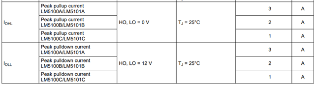
Also can the peak current achieve 4A if both drivers are driving loads (e.g. large capacitive) in-phase?

Kind regards,

LM

  • Hi LM,

    Thank you for reaching out! I appreciate the feedback on the datasheet figures. When looking at the figures, you can treat the output voltage as the voltage across each FET. When Vin = 12V and the gate voltage is still at 0V, the source current will be at a max. As the gate voltage rises to 12V and there is a total of 0V across the FET, the source current will be at a minimum.

    The LM5100B is rated for 2A of peak output current:


    If you think you will need 4A, a half-bridge driver like UCC27211A might be a better fit for this application.

    Best,

    Alex Weaver

  • Hi Alex,

    I see, thanks a lot for the explanation!

    I have a few more questions if that's ok.

    1. Does the power supply for this gate driver LM5100B need to be able to provide 2 A continuous/peak ? My VDD is 12V.

    I've noticed that some of the development boards like UCC27288EVM (driver with 2.5-A peak source and 3.5-A sink current) have a PSU with a current limit of 0.05 A. Why is that?

    2. Also, what would you recommend as a bootstrap diode with the following requirements:

    Bootstrap resistor peak current: IBpk =  12 V - 0.6 V/2.2 ohm = 5.18 A

    Boostrap resistor average current: IBavg: 33 nC x 100 kHz = 33 mA

    I've had a look at the recommended options in the application note SNVA083 and dev board designs and it seems that a ultrafast diode with an average forward current of 1 A is usually selected. I'm worried about the peak current of the boot resistor of 5.18 A. Is there a rule of thumb for the surge current to safely cover this?

    Kind regards,

    LM

  • Hi LM,

    No, the power supply does not need to be able to supply 2A cts. Peak. We expect the gate driver to be drawing less than 1mA of quiescent current, and up to 3mA of operating current at 500kHz and VDD = 12V:

    I believe the UCC27288EVM you mentioned has a current limit of 0.05A to help prevent damage to the driver or power switches. If this current limit is being reached, there could be a short or some other malfunction in the circuit that we would want to catch before the driver is damaged.

    Is the boot resistor required to be 2.2-Ohms? You will have to choose between increasing the boot resistor size which will lead to an increase in switching losses, or choosing a larger boot diode that is capable of handling the expected peak current. The app note you mentioned (SNVA083) calls out a few fast-recovery diodes on page 6 that could help with your selection.

    Best,

    Alex Weaver

  • Thank you!