This thread has been locked.

If you have a related question, please click the "Ask a related question" button in the top right corner. The newly created question will be automatically linked to this question.

TPS548A29: Remote sense issue

Part Number: TPS548A29
Other Parts Discussed in Thread: TPS548B28, TPS548A28

Hi Team,

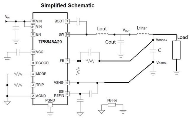
My customer want to improve output ripple performance, so they add a bead between inductor and load.

After solder the bead and using remote sense, IC will enter output OVP after power on, and they had do below test

1. Use local sense -> Output is ok, no issue

2. don't use bead between inductor and load, just short it -> Output is ok, no issue

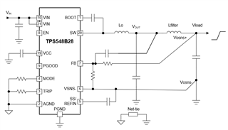
3. Add a capacitor between bead and load -> Output is ok, no issue

Could you help me check if this is abnormal condition or not? Thank you so much!

Best Regards,

Roy

  • Roy,

    The dc/dc converter is regulating a dc voltage.

    The feedback trace needs to connect near a capacitor

    so the voltage should be steady without transients.   

    You need a capacitor near the load to minimize voltage transients, adding

    a bead without a capacitor on the load side the load voltage would have a lot of noise and transients.

    With a bead and no capacitor, As the load current increases the load voltage droops causing the dc/dc converter to respond.

    If there is a capacitor on load side of bead, the load voltage is held up because the load current will be supplied by the capacitor. 


    David  

  • Hi David,

    Thanks for your feedback, because output capacitors are exist in all test conditions above, so I still have question about this.

    I think LC had filter the output waveform, then bead also filter the output waveform, I know the trace parasitic parameter between bead and load will lead to noise, but this noise may large enough to let TPS548A29 can't operate normally?    

    Best Regards,

    Roy

  • Do you have a drawing?   

  • Hi David,

    Do you mean like this?

    Lfilter is the bead, and C beside the Load is the capacitor added in test 3 above.

    Lout and Cout is exist in above 3 tests.

    Best Regards,

    Roy

  • 2022 FAE Summit call for papers BSR-MV second stage.pptx

    I need clarification of the issue.    You state customer adds a ferrite bead has an OVP and then state 3 scenarios where there is no issue. 

    If adding a ferrite bead, the loop response can change and the stability may be of concern.   The attached presentation discusses methods for lowering output ripple and tradeoffs. 

  • Hi David,

    Sorry for make you confuse. And thanks for your feedback.

    Below is 4 scenarios customer had test

    1. With bead(Lfilter in picture below), without capacitor at load side(C in picture below), use local sense -> work successfully

    2. Without bead, without capacitor at load side, use remote sense -> work successfully

    3. With bead, with capacitor at load side, use remote sense -> work successfully

    4. With bead, without capacitor at load side, use remote sense -> output OVP then shutdown

    I think the slide you share is discuss about how to improve performance of scenario 3, but customer's problem is they want to know why scenario 4 can not work successfully.

    Best Regards,

    Roy

  • Why does the customer  think adding only a ferrite bead would work for this configuration (see image below)?

    The ferrite bead  at lower frequency is an inductance.   

    Current can not instantaneous change in an inductor.    VL=L*di/dt.   

    A capacitor is needed on the load side of the bead to supply the energy to the load and maintain the regulated voltage. 

    Since there is no capacitor on the load, the Vload node voltage collapses when the load current increases.   

    and the Voltage overshoots when the load current decreases. 

    The device is responding to the voltage that is sensed on FB and VSNS-.   

    If the voltage that is sensed collapses, the device will respond to raise the voltage, 


  • Hi David,

    Really sorry that I misunderstood customer's problem. Let me clarify the condition.

    Customer already have capacitor in load side, and test scenarios as below

    1. With bead(Lfilter in picture below), with capacitor at load side(C in picture below), use local sense -> work successfully

    2. Without bead, with capacitor at load side, use remote sense -> work successfully

    3. With bead, with capacitor at load side, use remote sense -> output OVP then shutdown

    4. With bead, with capacitor and also add a high ESR capacitor at load side, use remote sense -> work successfully

    And customer also tried to parallel 2x 1 ohm resistor with bead in scenario 3, but  output still OVP then shutdown.

    I have two problem about this could you help me

    1. I would like to check the condition in the FAE summit slide you provide, do you know test result in slide use local sense or remote sense?

    2. Is it possible that because output ripple too small(8mV) lead to control loop have problem? 

    Best Regards,

    Roy

  • Yes, the ripple can be too low for TPS548B28.   There are devices will different control schemes and different feedbacks were experimented with. 

    Whether Local or remote sense, we should be able to make the TPS548B28 converter work.     

    The TPS548B28 works best with some ripple to help with stability.    I would recommend the hybrid feedback network

    Connect the resistor feedback circuit to the remote location for DC voltage regulation. 

    And capacitively connect to the local sense point, the ripple is greater and avoid the phase delay from the 2nd L

  • Hi David,

    Thanks for your feedback, and I would like to know does Cff had a maximum value

    I know Cff is use for increase stability, and different design have different suitable Cff value, but I would like to know if Cff have a maximum value should care don't exceed?

    Thanks!

    Best Regards,

    Roy   

  • A large Cff (> ~1000pF) on the TPS548A28 can cause an decrease load regulation accuracy from noise injected into FB pin.

    A resistor (Rff) is recommended in series with the Cff to eliminate the noise injection.   

    Also,

    If Cff is needed or was added  for stability, the Cff value should be within a "range" to benefit the control loop.

    When using a Cff, you are adding a Zero in the loop at a Fzero (Hz)=1/(2*3.14*Rhs*Cff).   

    And you are adding a pole Fpole (Hz)=1/(2*3.14*(Rhs//Rls)*Cff)

    The Cff  should be set to give the max phase boost near the Fco  (ie loop crossover frequency). 

    In the loop, the phase increasing  will start  at 1/10 of fzero and stop at 10*fzero for +90 degrees.

    Similarly, the pole will start decreasing  at 1/10 of fpole and stop at 10*fzero for -90 degrees

    So, the max phase boost will occur at Fmaxboost =(Fpole*Fzero)^0.5.

    If an extremely large Cff is used, it will be at a very low frequency and may not and help the loop.