Hi team,
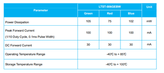
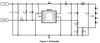
Please help to review LM3410 schematic, the LED spec is also attached below. Thank you.
Every light bard is 5S9P. Customer ask us to provide the design tool to confirm the design parameters.
Regards,
Alex
This thread has been locked.
If you have a related question, please click the "Ask a related question" button in the top right corner. The newly created question will be automatically linked to this question.
Hi team,
Please help to review LM3410 schematic, the LED spec is also attached below. Thank you.
Every light bard is 5S9P. Customer ask us to provide the design tool to confirm the design parameters.

Regards,
Alex
Hi Alex,
I have some question about the LED board and schematic, could you please answer these questions below first? Thanks!
1. Does "Every light board is 5S9P" mean that is a 5*9 matrix RGB LED board? Or could you please show me the light board?
2. Noted that LTST-006GEBW is an LED that integrates RGB lights and the every unit in schematic drives a light of one color. Does this mean that the total number of LTST-006GEBW is 45 (45R&45G&45B)?
3. Does the forward current of each light need to be 30mA just like the LED spec? Or is there a range? Because according to the R_set in the schematic, we can calculate the maximum current is 190mV/0.75Ω=253.3mA. So, if the forward current of each light is 30mA and the light board is 5S9P, my understanding is the total output current is 30mA*9=270mA>253.3mA. So, it can't meet the requirement.
4. Could you please tell me what the actual application is?
5. Does the schematic need to be considered the OVP protection circuit?
As for the input/output capacitor, inductor and the diode, I will check whether these components meet the requirements later.
Best Regards,
Jared
Hi Jared,
1. Yes, there are 45pcs of RGB LED (5x9) on the light board.
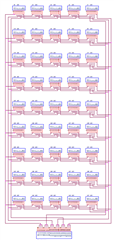
2. Yes.
3. Customer will use 0.7ohm afterward.
4. This is a confidential LED display evaluation project. No detail.
5. Is that need to add more component to implement OVP? I found there is a reference design AN-1996. I would like to know if it necessary to add D2/R3 in customer's schematic. And the location of output cap (C2/C4) are also different with what we suggest in datasheet. Please review customer's schematic I provided above and provide a final recommendation that to optimize the design. Thanks.
Regards,
Alex
Hi Alex,
1. my understanding is that the Vin=5V, Vout_max=2.6V*5V=13V, Iout=30mA*9=270mA. Am I right?
2. I have checked the input/output capacitor and diode, I think there is no problem with this. But I need to confirm the inductor with our design in detail.
3. According to the datasheet, as long as D2&R3 can realize the OVP function. I think if the customer don't consider this feature, it can be ignored.
After I confirm the inductor, I will reply to you ASAP.
Best Regards,
Jared
Hi Jared,
The calculation as below:
Green LED:
IF=30mA, VF = 3.5V, 5S9P
R1: 0.704 ohm; design use 0.7Ω (1% Standard)
(Assume 85% efficiency)
Inductor: 11.871uH; design use 15uH
Total LED RD (5S9P): 7.4ohm (13.33ohm for single Green LED)
Vout ripple: 200mV
C2: 3.25uF; design use 4.7uF
Please also help to check layout:
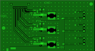
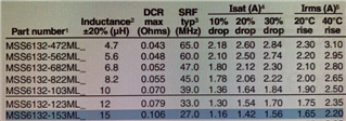
Inductor uses 15uH
Regards,
Alex