This thread has been locked.

If you have a related question, please click the "Ask a related question" button in the top right corner. The newly created question will be automatically linked to this question.

LMR36006: Output rails to max value

Part Number: LMR36006

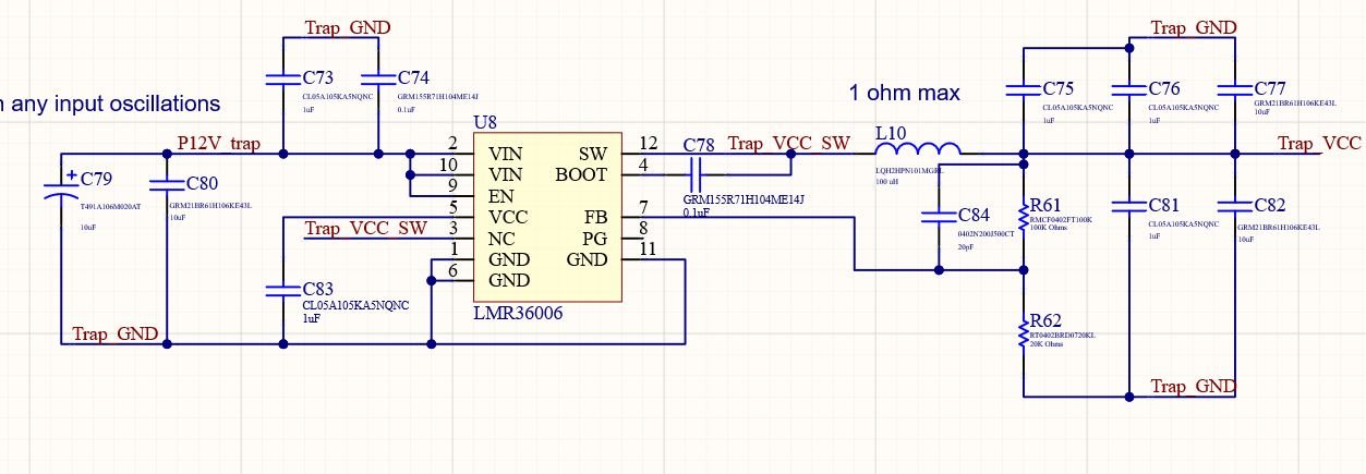
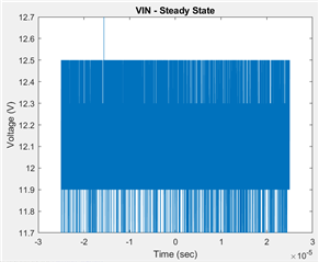
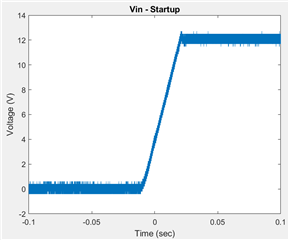
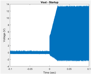
I've been trying to use the LMR36006 in a simple circuit to down-regulate from an input of 12V to ~6V, for a low power ion trap driver application. Despite my best attempts, the output will not appear to regulate itself and always rises up to nearly the input voltage, or ~11.8V. I'm running out of possible explanations and am hopeful someone can help me. The list of attempts I've already made are below.

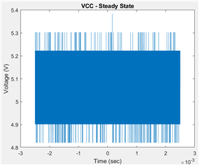
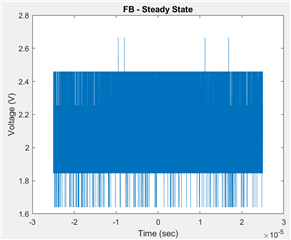
  • The FB voltage produced by my circuit is ~1.97V in this condition, which should notionally signal the LMR36006 to stop switching and let the output settle. Initially I was concerned the IC FB pin wasn't soldered properly, but I no longer think this is true (probing the IC directly and not the underlying pad shows the 1.97V)
  • Adding a dummy load resistor to increase the output load current above a low standby current level has no noticeable effect, beyond the output falling a bit (presumably due to ohmic loss)
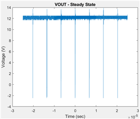
  • Output and input are not ohmically short circuited, it appears that the IC is operating normally but just never responding to any signal to not increase the output voltage. The switching behavior looks nominal to the best of my knowledge.
  • Replacing the IC with a spare had no noticeable affect.

Any ideas would be welcome - it's probably something simple, but so far this has eluded me.

  • Hi Michael,

    What's your operating conditions you are running at? (load current)? 

    The schematic as I see it looks fine. From what you've described, it looks like the part is entering dropout mode, which is strange as the feedback resistors seem appropiate.

    Can you provide a waveform of EN, VCC, BOOT-SW, and FB in steady-state?

    Can you also provide a waveform of VIN, VOUT, VCC during startup? 

    Finally, can you provide the layout? 

    Regards,

    Richard

  • Apologies for the delay Richard - other tasks took priority over the last 3 weeks.

    Load current varies from ~0 --> 50 mA at the output - the system is low power.

    These measurements don't have ideal ground references, so please excuse the excess noise.

    Steady state EN (tied to VIN):

    Steady state VCC:

    Steady state BOOT-SW:

    Steady state FB:

    Steady state Vout:

    Startup VIN:

    Startup VOUT:

    Startup VCC:

    Layout (quasi-3D view):

    Layout (2D view):

  • Hi Michael,

    Sorry for the delay in response as I've been out of office. From what I understand, it does look like the IC thinks it is in dropout behavior. It may have something to do with the layout? Looks like there's a violation in the 2D view. I added the engineer in charge of the E2E forums this month to help with the issue.

    Regards,

    Richard

  • Thank you Richard - for context, the 2D view layout violation is just a standard violation for <10 mil spacing between regions without solder mask.

  • Hello

    Be sure that you have a ground plane connecting the input caps and IC ground.

    Also, be sure that the two VIN pins are tied together.

    You might want to double check that the correct values of resistors were stuffed for the FB divider.

    Thanks

  • Hi Frank,

    There are indeed several ground planes connecting input capacitor returns to IC GND, on several layers.

    The FB divider was already confirmed given it produces ~2.1V given an output of 12V, which would nominally trigger the LMR36006 to let the output voltage relax to its target value.

    Visually both Vin pins are soldered properly, and they are tied together in the design.

  • Hello

    I don't see anything wrong in the schematic or layout.

    You might want to try a different slew rate on the input; either faster or slower to see if that has any effect.

    Thanks

  • Hello

    I noticed that your inductor is rather large and has a rather large resistance.

    For this design you would use an inductance in the 10uH range with a much lower resistance.

    You might want to try another inductor.

    Thanks

  • Hi Frank,

    I can try adjusting the inductor, but do you know of a reason why an inductor that is oversized would cause the LMR36006 to not regulate properly? I can't see any such reason.

  • Hello

    It may be the large resistance.

    Thanks

  • That still doesn't make sense to me (why would a large series resistance pose a problem? If anything it would just burn more power, but you'd still expect the regulator to regulate effectively the voltage found at the output of the inductor), but regardless, an attempt to replace the inductor with a 1 uH replacement (95 mohm DC resistance, DFE201210U-1ROM=P2) did not change the outcome. The feedback voltage still reads as ~1.95V, and the output is still effectively 12V, albeit with more ripple now than before.

  • Hello

    Can we see a better image of the output voltage waveform.

    The devices your tried may have been damaged by mishandling or ESD.

    You may want to try to get the EVM for this device and make sure it is working with your input

    and load and then put your components on the EVM to see if the issue shows up on the EVM.

    Thanks

  • Hello

    I will close this post due to inactivity.

    Thanks