This thread has been locked.

If you have a related question, please click the "Ask a related question" button in the top right corner. The newly created question will be automatically linked to this question.

LM25184: Regarding Drain waveform with RCD and R2CD snubber.

Part Number: LM25184

Hi,

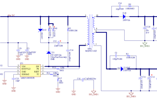
This is Pankaj working as a Hardware Design Engineer and currently working with a 5W flyback convertor with LM25184NGUR Switch IC with inbuilt MOSFET.

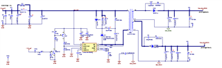
My Design: Vin = 6V to 14 VDC and dual output as Vout1=8.5V/675mA and Vout2= 8.5V/50mA and transformer turn ration is 1 (used 10::10:10 uH inductance) and leakage inductance is approx 1.2uH, considered = 85% efficiency.

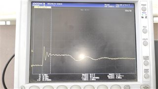
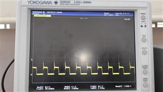
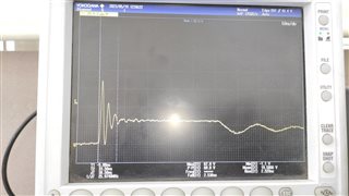
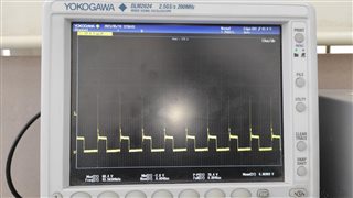
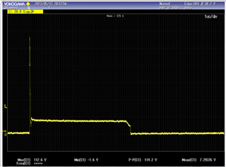
Problem Statement: Drain waveform pk-pk Voltage comes around: 105Vpk-pk and when trying to tune with RCD snubber then also it is not going to reduce than the 80Vpk-pk and when trying with the Z-D snubber with RC value R=6.8E and C=1nF then it comes in a range to 50Vpk-pk, my concern is that I am not able to reduce the mosfet peak using RCD or R2CD snubber circuit, I do not want to use Z-D snubber, In datasheet also suggested Z-D snubber, so any specific reason to use z-D snubber with this IC?

Also, it gets failed the RE  test at 80MHZ and its harmonics at 160 MHZ.

Tried Various iterations with the RCD snubber with its calculated value also but it the remains same.

Attached is the CKT for your reference.

BR,

Pankaj

  • Hi Pankaj,

    The ZD snubber is useful here because it has a well defined and consistent clamping voltage. If you are able to pick a zener diode that is able to be at the reflected SW node voltage, you may be able to clamp the ringing early. As shown in your waveform, with a RC snubber, you are able to dampen the ringing quickly, but it does not help you reduce your amplitude swinging by that much. 

    Regards,

    Richard 

  • Hi Richard,

    Yes with the Z-D + RC number values R=6.8E and C=1nF, I am able to damp this peak amplitude to 45 Vpk-pk, my concern is with the RCD snubber and the above waveform is with RCD Snubber values R=3.3K, C=300nF and Didoe part#S2M-E3/52T, kindly suggest why I am getting this 100Vpk-pk with RCD snubber or suggest the values for  RCD snubber asap.

    Regards,

    Pankaj

  • Attached are the referenc waveforms with Full Load and 50% Load with Z-D + RC snubber where R=100E and C=100pF.

  • Hi Pankaj,

    Just wanted to clarify a bit more. Are you just using the 3.3K, 300nF, and diode without the Z-D portion?

    One thing I noticed is that you may want to use a schottky diode instead of a regular diode. I've attached a blogpost here explaining a method on how to calculate the snubber network. You may try this:

    https://e2e.ti.com/blogs_/b/powerhouse/posts/calculate-an-r-c-snubber-in-seven-steps

    Another thing you may try is to try adjusting the snubber values across the flyback diode. It is possible that the ringing is exacerbated from there as well. 

    Regards,

    Richard

  • Hi Richard,

    Good morning,

    Just wanted to clarify a bit more. Are you just using the 3.3K, 300nF, and diode without the Z-D portion? >>> Yes I have used RCD without the Z-D portion.

    One thing I noticed is that you may want to use a Schottky diode instead of a regular diode ->>> I have used the Ultrafast diode and high voltage general purpose diode as well, and found with the ultra-fast diode I got 80MHZ rining over the drain waveform and that was reduced with the general purpose diode.

    I have tried various different values and played a lot with the R-C values but it didn't work as expected.

    Regards,

    Pankaj

  • Hi Pankaj,

    Unfortunately, I don't think there's a way to avoid the Z-D portion in your case. I think you will need to include the Z-D portion in order to minimize the amplitude of the ringing.

    Regards,

    Richard

  • Hi Richard,

    Sorry for the late reply, yes i get reduced with the Z-D portion as i told you earlier the peak voltage to 50Vpk-pk  with Z-D + RC snubber, but why RCD not working in my case, and the value of R=6.8R and C=1nF and with change in R-value the peak is changing.

    can you share your views as why Z-D is requied in my case.

    Regards,

    Pankaj

  • Hi Pankaj,

    The ringing has two components, the amplitude and ringing. The Z-D snubber primarily controls the amplitude of the ringing, while the RC snubber primarily controls the duration of the ringing. 

    In this case, I actually think your RCD circuit is functioning, but not in the way that you expect (reducing amplitude). That is primarily the function of Z-D network.

    In the reference design (https://www.ti.com/lit/an/snvaa28/snvaa28.pdf?ts=1685131722080&ref_url=https%253A%252F%252Fwww.ti.com%252Fproduct%252FLM5181-Q1), you can see that there is a Z-D network in parallel to an R-C network. 

    Regards,

    Richard