This thread has been locked.

If you have a related question, please click the "Ask a related question" button in the top right corner. The newly created question will be automatically linked to this question.

LP5890: CCSI Communication on STM32

Part Number: LP5890

Hi TI Team,

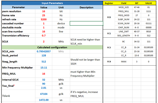
After much experimentation with an STM32G071 Nucleo board, I have still not been able to achieve lighting up the LP5890 EVM board. I have gone through the supplied sample code and converted it to STM32 HAL drivers. I have also used the LP5890 Register Map Generation Tool to make sure the registers are setup correctly.

I am currently running my SPI at 2MHz Baud Rate. I have set up a timer to run continuously at this same frequency. 

Here is a screenshot of what I'm currently seeing:

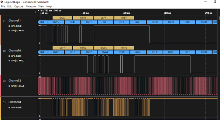
Channel 2 is the timer setup to be the clock, it is attached to SCLK on the EVM board. Channel 3 is the actual SPI clock on the Nucleo board. I am getting the same thing back (0xAA10 for W_CHIP_INDEX) on the MISO line that I am putting out on the MOSI. I am not seeing any other movement on the SPI lines besides this.

  • Hi Evan,

    First of all you already did a great work and we can see that the shifting through LP5890 is working. However, the data analyzed as 0xAA10 (on Channel 0) uses the Channel 3 actual SPI clock as reference. For the LP5890 Channel 2 would be the reference. This means that on Channel 1 you have 0 (start bit) 0x2A90 and then another 2 zeros which violates the CHECK BIT. It is therefore required to have back-to-back SPI transmission to avoid the LP5890 captures cycles where SPI is not transmitting. Below is the capture for W_CHIP_INDEX on the LP5890 EVM.

    Another item I would like to highlight is the 2 MHz. The internal GCLK should be in the range between 40 MHz and 160 MHz. With the maximum multiplication of 16 it means the minimum SCLK frequency should be 2.5 MHz.

    Best Regards,

    Ben

  • Hi Ben,

    Thank you for the feedback and for the image provided. I get what your saying that the LP5890 is using the generated clock as a reference for the incoming data from the micro, but I'm unsure of what you mean by having a "back-to-back SPI transmission."  Are you saying to send the same thing twice?

    Also, I came to using 2MHz based off using the following Register Map Generation Tool configuration:

    Based off of the information shown in the table, I believe that 2MHz should be efficient with the parameters I put in.

    Thanks again for your help.

  • Hi Evan,

    With "back-to-back" I mean that there should be no delay between the transmission of different bytes. I don't know if you are using DMA, but that is normally a good option to prevent delay.

    Looking at your configuration, I should remind you that the Internal GCLK should be at least 40 MHz. This is mentioned in Section 8.3.3 from the datasheet. In addition, the Tblank at 1472us is quite long and might have some visual flickering. You can reduce that by changing the refresh rate. Several hundreds of microseconds is normally better. It is possible to distribute the blank time over segments and subperiods as described in Section 9.2.1.5 in the datasheet. However, with only several hundreds over microseconds that is normally not needed.

  • Hi Ben,

    I am indeed using DMA on my SPI transmission and receive. I am unsure if I am getting the right data. Probably not if the protocol looks wrong on the logic analyzer. Are you familiar with the STM32 HAL drivers? Would you be able to help me if I shared my converted code with you? My guess is I am doing something wrong in the code. I'm very close and have been working on this problem for a while, I would greatly appreciate your help in this regard.

    In the meantime I also briefly explored using I2S protocol. You had suggested using it in my other forum post. The problem with that, at least on the board that I am using, is that the maximum frequency is 192kHz, well below what I would need for a clock here. Also, this board only supports Half-Duplex communication, which I don't think would work with the SIN, SOUT pins on the LP5890. So it looks like I'm stuck trying to use SPI here.

  • Hi Evan,

    I'm not very familiar with STM32 HAL drivers, but I could still have a look. I have sent you a friend request to be able to shared the code.

    For I2S, I think the 192kHz is maximum audio frequency. However, each audio sample can be 16 bits. That would mean that the serial clock would run at 3.072MHz and for stereo even at 6.144MHz.

    To enable the readback, you would indeed have to use a second I2S module. Another option is to use a SPI-slave module which is only enabled during the time you are expecting to receive data.