Other Parts Discussed in Thread: TPS23751, TLV431A,
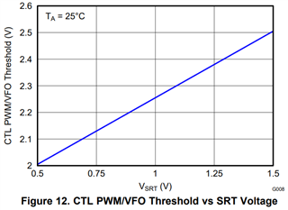
From TPS23752 datasheet "8.2.2.7 Setting the PWM-VFO Threshold using the SRT pin" as below.
How could I know the threshold between PWM and VFO on output loading?
Could I get the formula of threshold between PWM and VFO on output loading?
8.2.2.7 Setting the PWM-VFO Threshold using the SRT pin
The TPS23751 and TPS23752 internally compares modified voltages at the SRT and CTL pins to determine the
operating mode. The designer should consider the light load operating point (considering the value of VCTL)
where synchronous rectifier (M2 in Figure 32) gate drive and switching losses nearly match conduction losses of
the rectifier diode (DOUT in Figure 32). Typically, the designer characterizes circuit efficiency, output load, and
control pin (VCTL) voltage and then select the transition point. Both VFO → PWM (occurs at higher load current
due to natural hysteresis) and PWM → VFO (occurs at slightly lower load current) transitions should be
considered when choosing the VSRT setpoint. As an example:
1. Assume that the desired efficiency transition threshold occurs at 18% of full load and VCTL = 2.0 V
2. Determine where to set VSRT.
(2)
3. Set VSRT using a voltage divider from VB to ARTN as shown in Figure 32.
4. Choose RSRT1 = 100 kΩ and then calculate RSRT2 as follows:
(3)
5. Select 11 kΩ for RSRT2.