This thread has been locked.

If you have a related question, please click the "Ask a related question" button in the top right corner. The newly created question will be automatically linked to this question.

TPS2640: Power Mux

Part Number: TPS2640
Other Parts Discussed in Thread: TPS2660, SN74LVC1G14

Hi Team,

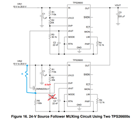
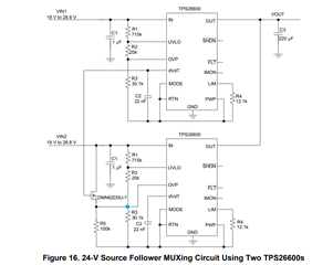
Can you suggest most simple power mux with TPS2640 ( there is no need for fast switchover time). ( eg FLT and SHDN pin) 

Input 1 ( Always has priority)

Vin1 from 12V to 24V


Input 2 

Vin2 from 5V to 25V - but it should only work from 12V to 24V ( when 5V then it is UV lockout activated)

-> when only input1 connected it powers output from 12V to 24V

-> when only input2 connected it powers output from 12V to 24V ( 5V to 12V is in UVLO)

-> when input1 and input2 connected, if input1 (from 12V to 24V) then input1 powers output regardless of input2 voltage

-> when input1 and input2 connected, if input1 (in UVLO or OVP state)  then input2 powers output .

In this case when input 2 powers output and input1 in UVLO, will the current flow from input2 to input1 through reverse current blocking mosfet of the efuse1 ? 

Best Regards,

d.

  • Hi d,

    Please refer section 5 at page 14 of this app note: https://www.ti.com/lit/an/slva811a/slva811a.pdf.

    It shows power muxing using TPS2660(TPS2640 is p2p with TPS2660). Since it has b2b fet reverse current will not flow.

    Regards

    Kunal Goel

  • Hi Kunal,

    1) In case using the your suggested schematic from slva811a app note.

    -> how is the external mosfet selected, and how to calculate R5?

    -> how is the second efuse2 UVLO and OVP calculated?

    -> do you have a reference design where this circuit is implemented?

    -> when efuse1 in OVP mode, will then also the dVdT pin voltage drop like efuse1 in UVLO mode?

    2) because we don't need fast switchover, can we connect the FLT pin of efuse1 via inverter (SN74LVC1G14) to SHDN pin of efuse2 ?

    Best Regards,

    d.

  • Hi Kunal,

    any update regarding our questions?

    Br,

    d.

  • Hi D,

    I remember replying somehow it did not get through.

    1) In case using the your suggested schematic from slva811a app note.

    -> how is the external mosfet selected, and how to calculate R5?  FET VGS should be more than 4-5v rated, VDS should be more than eFuse VIN, R5 is to limit current as FET will be in saturation region when on so keep FET in SOA we will need R5.

    -> how is the second efuse2 UVLO and OVP calculated? That you have to decide what values you want to keep.

    -> do you have a reference design where this circuit is implemented? no

    -> when efuse1 in OVP mode, will then also the dVdT pin voltage drop like efuse1 in UVLO mode? yes

    2) because we don't need fast switchover, can we connect the FLT pin of efuse1 via inverter (SN74LVC1G14) to SHDN pin of efuse2 ? yes

    Regards

    Kunal Goel

  • Hi Kunal,

    if we want to use OVP approach as in SLVA811a  figure 16 and want to have

    UVLO1 = UVLO2 = 8V and OVP1=OVP2 = 28V, how are the resistors calculated?

    It seams that eFuse2 in Figure 16 in SLVA811a uses the Internal OVP =33V ?

    Remove R3, and use R1 and R2 to set ULVO, and add R to set OVP with R and R5 ?

    Br,

    d.

  • Hi d,

    Fig 16 sets configurable UVLO and OVLO on both devices. if you need that please follow resistor divider like fig 16. You can use design calculator on product page or refer application section in datasheet.

    Regards

    Kunal Goel

  • Hi Kunal,

    are you shore? isn't here maybe a missing connection like this marked in blue?

    because if there is no connection here then OVP only has a 100k pull-down ( internal 33 OVP) ? , and if there is a missing connection on figure 16 then the R3 from calculator is in fact parallel connection of R5 and R3 from SLVA811a =23kOhm -> OVP=39V =! 33V as stated and UVLO = 21V =! 18.5V as stated

    Looking forward to your comments, if there is an error in SLVA811a ( the missing dot connection.)

    Best Regards,

    d.

  • Hi d.

    That is a mistake in image in app note. It should be how you pointed out. 

    Regards

    Kunal Goel