This thread has been locked.

If you have a related question, please click the "Ask a related question" button in the top right corner. The newly created question will be automatically linked to this question.

Device getting damaged by powering by Passive PoE, using LM51551DSS switcher and TPS2373-3RGW PD Controller


Hi Team, 

We are designing an Access Point which gets powered by POE BT standard adaptor. 

We  have used TPS2373-3RGW PD Controller and LM51551DSS switcher IC in the SMPS section. 
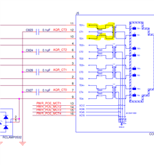
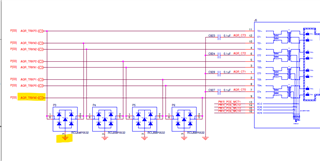
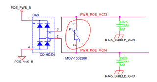
When we are powering the device by Passive POE, the signal lines of the ethernet lines are getting damaged, i.e. the impedance of the signal lines is getting low. 

This is a production blocker for us and we need to provide some resolution as soon as possible. 

HFCI_AP88_Ethernet.pdf

  • Hi Atoshi, 

    Thanks for reaching out to us!

    "the signal lines of the ethernet lines are getting damaged"

    Do you mean the eight Ethernet wires (1 to 8) got damaged after passive PoE test? What voltage you applied when doing this test?

    "the impedance of the signal lines is getting low"

    Do you mean, for example, in PR12, the impedance between wire 1 and wire 2 gets lower? For DC resistance it should be close to 0 since they are connected in inductance. For AC resistance it may depends on multiple factors like magnetizing inductance, CM choke, capacitance, and so on.

    Best regards,

    Diang

  • Hi Diang, 

    Thanks for the reply. 

    Kindly find the inline response,

    Do you mean the eight Ethernet wires (1 to 8) got damaged after passive POE test? --> either of the signal pairs are getting damaged. In multiple cases, 2 pairs are also getting damaged.

    What voltage you applied when doing this test? --> 48V POE Voltage was applied on RJ45 Connector.

    When we are saying "the impedance of the signal lines is getting low" , we are checking the impedance of the signal lines with respect to ground, where we are getting low impedance i.e. 1.5k whereas when we are checking the impedance of signal lines with respect to ground, we are getting 5.9K impedance. 


    For your reference, we have attached the points we are are checking the impedance with respect to ground. 

  • Hi Atoshi, 

    Thanks for your reply. Based on my experience, if fault like short circuit happens after the PD's hotswap, the PDIC is likely to be damaged. But for your case, the wire was damaged, so it could be before the PD's hotswap.

    For 8 ethernet wires, the PoE pairs is PR12, PR36, PR45, and PR78. I am wondering if P4 connects to PR34? 

    And RClamp0532T has 5-V working voltage, but PoE has 37-57 V input voltage. Could you check if they can be used here?

    Besides, can PWR_POE_MCT4 block AC voltage since it is before the rectifier? 

    Best regards,

    Diang

  • Hi Atoshi, 

    By the way, the capacitance between VDD-VSS should be less than 0.15 uF. Normally only one 0.1-uF capacitor is used.

    Best regards,

    Diang

  • Hi Diang, 

    Thanks for your reply. 

    Kindly find the inline response to your queries. 

    For 8 ethernet wires, the PoE pairs is PR12, PR36, PR45, and PR78. I am wondering if P4 connects to PR34? --> Yes, P4 is connected to PR36, but it is not limiting to 1 single MDI pair. The MDI lines are getting damaged on random manner. 

    And RClamp0532T has 5-V working voltage, but PoE has 37-57 V input voltage. Could you check if they can be used here? --> We have used RClam0532T on the secondary side of the Magnetics with the MDI Lines, which is having a voltage of +2.5V to -2.5V. So we are in the range of 5V only. The PoE voltage of 37V-57V is on the primary side of the magnetics, which is going to our SMPS Section.

    Besides, can PWR_POE_MCT4 block AC voltage since it is before the rectifier? --> The MOV that we have used before the rectifier is to suppres any transient spike coming from the source. The rectifiers are used for converting two directional voltage source to single direction voltage and is also having the working for reverse protection.

    By the way, the capacitance between VDD-VSS should be less than 0.15 uF. Normally only one 0.1-uF capacitor is used. --> We have got the schematics reviewed by TI Team. This point was not mentioned earlier while the review. We will try to implement this point but this is going to add some additional filtering. 

    Kindly let us know what will effect if we use 3 x 0.1uF capacitors between VDD to VSS.

  • Hi Diang, 

    We are using RJ45 Connector with integrated magnetics. When we are powering the device by PoE, a potential is getting build on the secondary side of ethernet MDI interface and causes damage to the Ethernet PHY pins which are secondary side MDI lines. 

    On the secondary side, we have used RCLAMP0532 TVS Array for surge protection purpose, but still we are getting a voltage of 12V on the MDI Lines for which is randomly damaging the Signal Pairs. 

    Kindly assist us to provide a solution for this issue. As it is acceptable that device should not power on with Passive PoE but it must not damage in any condition.

    Please guide us how to rectify this issue on priority.

  • Hi Atoshi,

    Thanks for your reply.

    The max capacitance VDD-VSS in IEEE 802.3 BT standard is 0.15 uF.

    For your case, the wire was damaged, so it could be before the PD's hotswap. If short-circuit happens after the PD's hotswap, it should trigger the PD's hotswap's overcurrent protection. I would recommend to do the PoE injector test without PD connected first. 

    Another possible thing is the isolation voltage. For PoE with up to 57-V stable voltage and transient voltage may reach 100V, it is important to leave a sufficient space.

    Best regards,

    Diang

  • Hi Atoshi,

    We will close this thread for now. Please reply if you have any further questions.

    Best regards,

    Diang