This thread has been locked.

If you have a related question, please click the "Ask a related question" button in the top right corner. The newly created question will be automatically linked to this question.

LM3410: Need equivalent schematic to replace FAN5331SX

Part Number: LM3410

Hello,

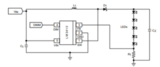
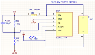
We are trying to replace the FAN5331SX in the schematic below with an LM3410 but the output goes to VIN and stays there. If possible, could someone please let us know if it is possible to create a 13v output with the LM3410 in this schematic but possibly with different inductor and resistor values? Input and output caps (not shown) would be 4.7uF.

Application: driving an OLED display with 13-13.5v 16-27mA (typ) (19-32mA max.)

Could you please let me know if you may require any further details?

Thanks very much!

Cheers,

Rodney

  • If possible, could someone please check me on these? I have done a rough calculation and in order to get V(FB) = 190mV in the middle of the voltage divider and I(LED) being 32mA (max) and Vout = 13.5v, Vin(min)=5v and Freq=1.6MHz, would I be looking at R8F = ~413.3ohms and R9F = ~5.9ohms and L1 = ~10.4uH ?

  • Rodney, 

    You can select 10uH inductor,  Input and output caps 4.7uF.

    While for FB pin and feedback, you need to change schematic as shown in datasheet. The two devices use different control mode (FAN5331 voltage mode vs. LM3410 current mode)

    It won't work if you just follow FAN5331 schematic, the LED output current will not be able to regulated.