This thread has been locked.

If you have a related question, please click the "Ask a related question" button in the top right corner. The newly created question will be automatically linked to this question.

TPS25750: I2C line held low after charger write command

Part Number: TPS25750
Other Parts Discussed in Thread: BQ25731,

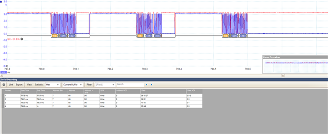
We are having an issue on the I2c bus when the PD chip communicates with the charger chip (BQ25731). The clock line is stretching when we switch/request a different voltage level using an external PD SINK device.
We have our own custom board based on the EVM.
The above is tested with the GUI-generated firmware using the TI tool for firmware customization.

This is the configuration file:

{"questionnaire":{"version":"7.0.4.6","answers":[0,3,3,0,1,2,1,null,1,null,2,12.6,1.536,null,null],"options":{},"configID":"0000","vendorID":"0000"},"configuration":{"data":{"selected_ace":[{"register":6,"data":[0,0,0,0,0,0,0,0]},{"register":22,"data":[10,48,48,77,0,0,0,0,0,0,7]},{"register":50,"data":[4,168,42,44,145,1,38,44,209,2,0,44,177,4,0,44,65,6,0,0,0,0,0,0,0,0,0,0,0,0,0]},{"register":51,"data":[4,44,145,1,16,44,209,2,0,44,177,4,0,44,65,6,0,69,65,6,0,0,0,0,0,0,0,0,0]},{"register":92,"data":[240,0,0,0,0,0,0,0,0,16,0,0,192,0,0,0,48,0,0,0,0,0,0,0,192,12,0,0,0,0,0,0,0,0,0,0,0,0,0,0,0,0,73,75,0,0,0,0,0]}]}}}

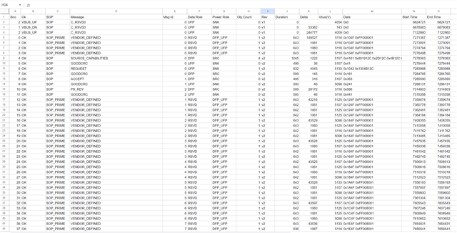
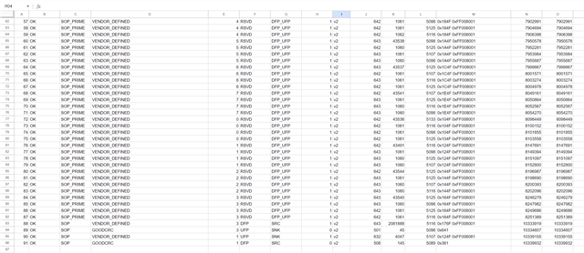
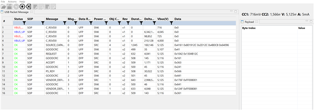
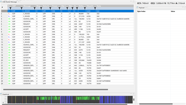
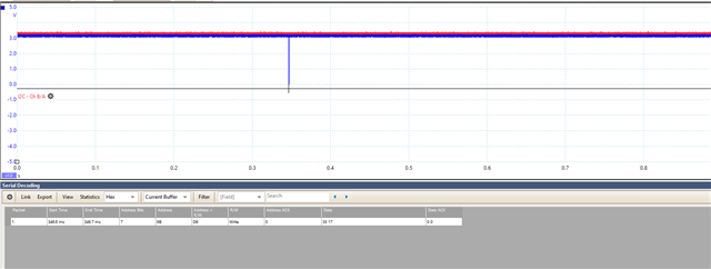
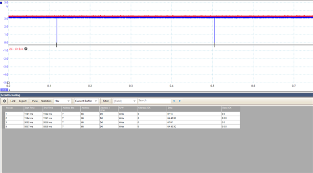
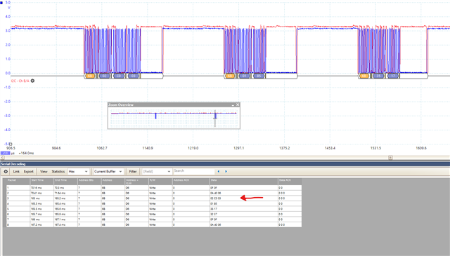
We've probed the line to monitor the data traffic and here is what we got:


the above sets the charge chip otg voltage to 20v, this is set correctly but no further I2c communication between the two chips "clk line is held LOW" . 

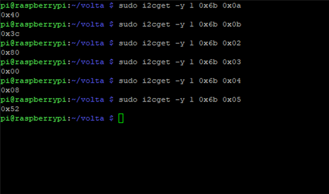
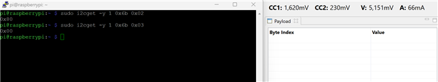
In debugging, we have used the 4CC commands 'I2Cw' and 'I2Cr' to read/write to the charger chip from the PD chip which worked fine without any issues (writing the same sequence of data we probed from the line but with different/more delays) we don't see the issue when the commination is driven by the gui-generated firmware.

Could you please advise.


  • Hi Field,

    The charger chip we are using in conjunction is the "BQ25731." We have received the binary file for the PD chip. However, the problem we are facing is that the chip does not set the charging power according to our specifications:

    We intend for the device to be configured as a Dual Role Port with "Try.SRC" enabled. The source PDOs have no issues and are as follows:

    Source PDOs:

    5V 3A
    9V 3A
    12V 3A
    15V 3A
    20V 3A

    The sink PDOs are defined as:

    Sink PDOs:

    5V 3A
    9V 3A
    12V 2.5A
    15V 2A
    20V 1.5A

    The desired maximum charge current is 1920mA, and the charge voltage is set to 21V (5S 2P battery pack). Our preferred Data Role is "UFP."

    I have also attached  screenshots of PD logs  of the recent binary. They show the logs for when connecting the port to two different wall chargers.


    The source capabilities message in line 9 contains these "0x4161 0x801912C 0x2D12C 0x4B12C 0x6412C".

    We kindly request your assistance in providing us with an updated file as quickly as possible, as we are currently in a critical stage of development.


    Kind regards,
     Ahmed
  • Hi Ahmed,

    Thank you for the detailed info and summary, I definitely appreciate it!

    I am unsure of why Conner's .bin file did not work. Did you use the 'Gaid'/'GAID' commands that he linked earlier in your discussion to reset the device and try the .bin?

    I have created two new .bin files. Could you try using the A3.bin file first and if that proved unsuccessful try the A2.bin? A2 may not work, but it might be worth a shot in the event that A3 does not. Please let me know if either of these work for you or any pertinent details.

    https://e2e.ti.com/cfs-file/__key/communityserver-discussions-components-files/196/E2E_5F00_WT_5F00_A3.bin

    https://e2e.ti.com/cfs-file/__key/communityserver-discussions-components-files/196/E2E_5F00_WT_5F00_A2.bin

    Thanks,
    Field

  • Hi Field,

    Both of the files you've sent did not work, as you can see in the screenshot the source capabilities are received but the PD chip always requests the first PDO, and also the charge voltage and current are not set. 

  • Hi Ahmed,

    Can you confirm you are using the GAID command to reset the device and that you are flashing properly or explain the process that you are using? Below is a new one, but again I am unsure if this one will work if the previous one did not. The charge voltage has been and should be set to 21V and the charge current to 1920mA. If possible could you try using the customization tool on your end? Or does this have the same end result?

    https://e2e.ti.com/cfs-file/__key/communityserver-discussions-components-files/196/E2E_5F00_7041.bin

    Additionally can you get me detailed captures of the I2C bus from the following conditions:
    It is best to get a scope capture of the PPHV (the node between the cobra and the BQ25731 as well as the 2 I2C lines)

    • Power Up (Make sure that boot works and the Charger is configured properly)
    • Connect to Sink (Make sure that the source current and voltage are set properly)
    • Connect to source (Make sure that the charger is enabled properly)

    Something to note is that the BQ25731 could run into issues if too much capacitance is present and we attempt to write before it is fully powered up.

    Can you also provide me a scope capture showing the clock lockup and what happened before?

    Thanks,
    Field

  • I will get the scope captures and other requested info as soon as I can. 
    Yes I have tried used the customization tool but I got the same result. 
    We flash the binary file to the an eeprom and it's the same way we used since the first posted in this thread and we got many issues resolved, I will  also share the details of how we flash the eeprom.

    While I get what you requested, how could we expedite this, could we arrange a meeting or video call or anything that could help tackle the issue quicker cause we currently just do one trial per day, if it doesn't work we have to wait for another day.

    Thanks Field,

  • Hi Ahmed,

    I understand. I will check with the other experts once you have the requested information and work to get something, a meeting or call, set up for next week, assuming we can have the information by early next week? This will be needed before I can set something up, in order to gather information and receive proper assistance. 

    Thanks,
    Field

  • Thanks Field,

    I will have everything ready by early Monday.

  • Hi Ahmed,

    Great! Like I said this will be a great help. Please note that there is a public holiday in the USA on Monday and we won't be in office till Tuesday.

    Thanks,
    Field

  • Hi Field,

    Here is the link to a document I made with some screenshots of the logs and I2C bus:

    https://docs.google.com/document/d/1moggqyx7BrRQGBLvtF65MxX602VnSWg-/edit


    Here is the folder for the source files and images if needed: I have screenshotted everything in the .word document. 

    https://drive.google.com/drive/folders/1QUAeeoJSUVQ3CDTM2coVY_fZfemcLWXq?usp=sharing

    To view I2C logs from source file “.psdata”  you need to install this software: https://drive.google.com/file/d/1NH_Dez0HasuGXmOaZ6qG0Dw0B5HYrZeu/view?usp=sharing

     Conner has already used the same link and installed it.

    The .bin file used is “ahmed_updated_20230828.bin” sent by Conner in Aug 28. The other files you've sent did not also work.

    Could we arrange a meeting to go over the issues or do you think the information is sufficient for you to resolve the issue?
    Let me know if you need anything else.


    Just in case the first link did not open for you, I'm copying the scope captures here as well:


    Testing:


    The .bin file used is “ahmed_updated_20230828.bin” sent by Conner in Aug 28.


    To view I2C logs from source file “.psdata”  you need to install this software: https://drive.google.com/file/d/1NH_Dez0HasuGXmOaZ6qG0Dw0B5HYrZeu/view?usp=sharing

     Conner has already used the same link and installed it.


    • We flash the binary file to an EEPROM, we have a python script to do that using SMbus I2C. We also have another file to verify and match the data on the EEPROM with the data in the .bin file. Python files attached in folder “Flash/ py” and “Flash/read_07_24_23.py”.


    • After the device is flashed with the binary file we reset the chip using the command “GAID” which works fine “logs in file (reset_log_i2c.csv or reset_log_i2c_pico.psdata)“.


    • When plugging into a DRP the PD chip makes a successful contract and becomes a source and provides power to the sink device, but tracing the I2C, it looks like the I2C clock stretches and stays LOW until we do a hardware reset every time. It happens only when we connect to a DRP port. We had this issue before, it was the issue we opened this thread for and we got it resolved previously (in Jun 23 in file “ahmed_final_binary.bin” sent by Conner, but it looks like it’s back again with this binary file.


    PD Logs “source file name (PD_LOGS_DRP_SRC.ccgx3)”:

    No issue on PD logs, and the power is set to 20V 3A


    I2C Logs “CLOCK STRECHING” “source file name (DRP_SRC_clk_stretch.psdata):


    • When plugging into a wall charger that supports PD, the clock stretching issue does not appear however, the charge current is not set correctly. The logic analyser I used misses some of the data so you might not see the whole I2C logs in this capture, but I went and read the corresponding registers on the charger chip. Charge Current Registers 0x02 and 0x03 are set to 0x80 and 0x00 which is not correct.


    Charger Chip Regusters


    PD Logs:

    Drawing 300mA only


    I2C SCOPE CAPTURE, “SOME LOGS MIGHT BE MISSING”:


  • Hi Ahmed, 

    So everything is working/fine except that the charge current and charge voltage registers are not being set correctly? I believe I have found the issue and I am working to resolve it and want to test it with the EVM. I will hopefully have this figured out and ready by at latest EOB tomorrow. Pending anything further can be discussed or arranged after that. I have sent you a request via E2E that we may discuss a potential meeting if this does not resolve your matters, please accept so we can dive into further details if needs arise.

    Thanks,
    Field

  • Hi Field,

    I have captured two issues not just one.
    first one is the charge current not being set correctly.
    The other issue is I2C bus crashing "clock stretching forever" when connecting to a DRP, PD contract is successful and the charger is configured but the I2C bus crashes immediately and we no longer have I2C comms. This is a similar issue to the one we had at the start of this thread you can go through the early messages we had with Conner.


    Blue: I2C clock.
    Red: I2C data. 
      

  • Hi Ahmed,

    Thanks for the response. Please see the attached .bin file. This should correspond to the information you have provided and establish the charging current and voltage. The .bin file you are using and provided earlier seem to have been missing some information and I have gone head and appended the desired settings and should be reflected accordingly.  https://e2e.ti.com/cfs-file/__key/communityserver-discussions-components-files/196/Ahmed_5F00_Request_5F00_06SEP.bin

    In regards to the clock stretch, I must consult with another senior expert and loop them in on this thread in order to expedite this thread. If the above .bin does not solve the issue. Please see the following so we can receive their assistance.

    • Can you get a scope capture of the PPHV pin and SCL and SDA during this event that is causing the clock stretch?
    • The BQ25731 has a lockout if the voltage dips or has not fully risen yet.
    • If we can see the I2C lines and the input voltage to the charge chip which should be the PPHV pin of the TPS25750, they should be able to provide valuable assistance.

    Thanks,
    Field

  • Thanks Field,

    The recent .bin file fixed the two issue!!
    however, there's still a minor issue, when the port is connected to a partner DRP and when TPS25750 becomes a sink or we perform a power role swap from source to sink, the charge current is not set correctly.
    when in sink mode the charge current registers (0x02 & 0x03) should be set to (0xc0 & 0x03), which works well except in the case I mentioned.
    I probed the I2C line and I saw the data being sent from the TPS25750 to the charger chip (0xc0 & 0x03) which looks fine:

    However, reading the registers in the charger chip afterwards returned these values which are not correct:


    And when I try to change the registers value manually through I2C it does not accept it.
    I have checked the register 0x20 in BQ25731 to see if any errors but no errors were shown.


    Another question, when we perform a Data Role Swap to UFP, is TPS25750 meant to do reset it self?

    Regards,

    Ahmed

  • Hi Ahmed,

    That's great to hear! I do not know why this is happening, if the TPS25750 is writing correctly it could be an issue on the BQ end. I will reach out to the corresponding team to see if I can find out more information. But I think as mentioned earlier it may still help to get a scope capture of the PPHV pin and SCL and SDA. As it may be experiencing this lockout and not allowing the TPS25750 to write to it. Would you be able to provide this? 

    Thanks,
    Field

  • Hi Field,

    Here is the scope capture of SCL, SDA, PPHV and VBUS.

    Case: Power Role Swap from Source to Sink (OTG was on 20V 3A)
    The source files:
    (I2C capture)
    https://drive.google.com/file/d/1XeedqN1l4FVHPzDtF2LvPy8hH3Bi-Ek-/view?usp=sharing
    screenshot: the i2c data can be viewed in the table.


     (PPHV 'BLUE' and VBUS 'RED') 
    https://drive.google.com/file/d/1knyjChVwW_DGtD7kxl6xeFP7PaXtFcRu/view?usp=sharing
    screenshot:


    PD logs:


    To view the logs from source file “.psdata”  and if the screenshots I attached don't show what you need you can install this software: https://drive.google.com/file/d/1NH_Dez0HasuGXmOaZ6qG0Dw0B5HYrZeu/view?usp=sharing

    let me know if that's all you need.

  • Hi Ahmed,

    I am still looking into this. I'm curious if this is a timing issue as the I2C write is happening at ~165ms and the PPHV is reaching peak value at ~170ms. But this may be a non-issue, or I may be misunderstanding.

    If I am understanding your current problem is that when you are connected to partner DRP, and then as a sink/src->snk, the charging current is not being set correctly? So is the I2C writing this 02 0C 30 (packet #3 in the above) correctly, but we are not seeing it in the BQ25731 device? Is this accurate? 

    Thanks,
    Field

  • Yes, that's the issue we are encountering, and we are not seeing it in the BQ25731 device plus, writing to the charge current registers manually not through the PD chip does not work, the registers value does not change, why would this behaviour happen?.
    I have noticed that it intermittently worked about 2-5 times (src->snk). 
    could be a timing issue, but why would BQ25731 not change charge current register value? I always change the charge voltage and current together cause I know they need be written in 2 bytes. 

  • Hi Ahmed,

    I believe this may pertain to the lockout or reset on the BQ device, due to the timing as I believe the level needs to be at peak value before writing. And based on your above information it looks like it is writing approximately 3-5ms before the level has reached peak value. After discussing with another expert it might also be generally helpful to not write to BQ device during the first 200ms of power up as the register may be reset by the charger during the power up before/during this time.

    Thanks,
    Field

  • Hi Field,

    Yes the issue turned out to be BQ lockout due to hardware interference, I managed to fix it. Thanks so much for your help!!

    Can I request a binary file with everything we had on the last file but disabling all of the interrupt events except the "PlugInsertOrRemoval" event.

    I also have a question, what would happen if the dead battery flag is set? And when is it preferred to be cleared?

  • Hi Ahmed,

    This is good to hear! Attached is the new .bin file with all interrupts masked except 'Plug Insert or Removal'  https://e2e.ti.com/cfs-file/__key/communityserver-discussions-components-files/196/Ahmed_5F00_Request_5F00_14SEP.bin. These were the only changes that I made. Please let me know if this .bin does not work.

    If dead battery flag is set, it depends on the dead battery configuration you are using. This can be seen in Table 9-5 on page 45 and 46 of the datasheet linked here. There is also an application note linked here that goes more in depth on dead battery.

    Thanks,
    Field

  • Thanks Field.

    Is it possible to add a 300ms delay before reading the data from the EEPROM ? because we have an issue when the battery dies and the power is switched on VBUS the PD chip always goes into PTCH mode and we saw this power brownout on the I2C line.


  • Hi Ahmed,

    Does the device recover after this? In the mode register, after 300ms what is the Mode Register (0x03) set as, is it still in PTCH? Could you trying utilizing the PBMs command when this event is seen and seeing if this resolves the issue? It may be possible to write dummy read/write commands that may create this delay, but I would need to look more into this, as I don't know if it's possible to trigger during this specific event. 

    Thanks,
    Field

  • Hey Filed,

    Isn't PBMs command meant for loading the data from host/MCU? because we have the .bin file flashed into an EEPROM. I'm not sure how to utilize this command and what needs to be loaded onto the DATA1 register before issuing the command could you please show me the the process in details. The issue we are having is when no battery is connected (dead battery mode) and we plug in the usb-c "power is from VBUS", it looks like the PD chip does not find the eeprom on the I2C bus, look at the screenshot below "it's trying to read the data from eeprom at 0x55 but it's NACKED". Also see the voltage level when plugging the cable, it started communicating with the eeprom before reaching to 3.3v on SDA and SCL.


    I have also noticed the same issue when using one of the .bin files sent earlier ( “ahmed_updated_20230828.bin” sent by Conner in Aug 28), however, with this file resetting the chip with "GAID" command fixes it but not on the latest files you've sent.

    would be able to try this on dead battery mode? 

  • Hi Ahmed,

    Does the device operate normally after this or disconnecting the dead battery, or using a non-dead battery? Or does it stay in this dead battery configuration afterwards? I'm going to see if I can get another expert to assist with this as I am unsure of what may be going on. Please expect a small delay in response. 

    however, with this file resetting the chip with "GAID" command fixes it but not on the latest files you've sent.

    In regards to the above, I wonder if this may be because we have masked several interrupts. Could/Did you try the Ahmed_Request_06SEP.bin, and see if this worked with the gaid/GAID commands?

    Thanks,
    Field

  • Hi Field,

    I found the issue, it was hardware with I2C busses. Thank you so much for your assistance and I will let you know if any other issues occurred.


  • Hi Field,

    can I request two binary files similar to /cfs-file/__key/communityserver-discussions-components-files/196/Ahmed_5F00_Request_5F00_14SEP.bin

    you sent recently, but one with the port being configured as Source Only and the other file for Sink Only.

    Thanks,

    Ahmed

  • Hi Ahmed,

    I am currently out of the office and will be through the end of the week. When I return I will be able to provide you this information/material. Please expect some delay in my response accordingly.

    Thanks,
    Field

  • Hi Ahmed,

    Apologies for the delay, as I have been out of office. I have since returned and should be able to get this to you tomorrow. 

    Thanks,
    Field

  • Hi Ahmed,

    Please see the following:

    Sink: https://e2e.ti.com/cfs-file/__key/communityserver-discussions-components-files/196/Ahmed_5F00_Request_5F00_04OCT_5F00_sink.bin

    Source: https://e2e.ti.com/cfs-file/__key/communityserver-discussions-components-files/196/Ahmed_5F00_Request_5F00_04OCT_5F00_source.bin

    If these do not work, please let me know.

    Thanks,
    Field