Because of the Thanksgiving holiday in the U.S., TI E2E™ design support forum responses may be delayed from November 25 through December 2. Thank you for your patience.

This thread has been locked.

If you have a related question, please click the "Ask a related question" button in the top right corner. The newly created question will be automatically linked to this question.

TPS65020: Power up issue

Part Number: TPS65020

Hi team.

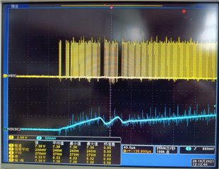
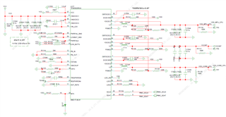
Customer found an issue during powering up. SCH is as below. And during power up, we found that the PWM will interrupt sometimes which cause the glitch of power up. Blue waveform is VDCDC2 and yellow waveform is PWM waveform. 
Could you pls help to analyze this issue and share some suggestion on it? Thanks a lot!


Thanks!

Rayna

  • Hey Rayna,

    I am still looking into this. In the meantime:

    1) Can you give the suggestions found in this E2E thread to the customer? It seems another customer has had this problem in the past.

    2) Is this issue only occurring on DCDC2? Or Is this behavior also seen in DCDC1/3? 

    Best,

    David Martinez

  • Hi Martinez,

    That's also Mindray issue. This issue has been a long time but haven't discussed the details.

    Occur in DCDC1/2/3.

    We also found that if DEFDCDCx connect to GND, then it'll be no power up glitch. If use external resistor, then it'll have glitch issue.

    So I was wondering if it's caused by external resistors wrong design, like too large resistance or anything wrong.

    Besides, the glitch shows that PWM switching will stop sometime, so another guess is maybe UVLO or any protection is triggered inside.

    Since I don't have the EVM, I was wondering if you could give some suggestion for more experiments. And Could you pls help to check the feedback circuit to confirm when PWM may stop.

    Thanks!

    Rayna

  • Hey Ruixin,

    So I was wondering if it's caused by external resistors wrong design, like too large resistance or anything wrong.

    1) According to the datasheet, the resistors are fine. Their sum is below 1M Ohm.

    2) I compared your schematic with the EVM schematic and nothing stood out to me as an error. Has the customer probed the input voltage or the output current to see how they are changing during this time? Seeing this may indicate if any protections are being triggered. 

    3) Is this affecting device functionality? I talked with some other members on my team and they said that this may be related to the soft-start function of the device. Since this is a legacy device, it may not be worth investigating if it doesn't hurt device functionality especially since resources on this device are limited.

    Thanks,

    David Martinez