This thread has been locked.

If you have a related question, please click the "Ask a related question" button in the top right corner. The newly created question will be automatically linked to this question.

LP87702-Q1: LP87702K-Q1 PG0 level question

Part Number: LP87702-Q1
Other Parts Discussed in Thread: AWR2944

Hi Team,

My customer report that PG0 is always '0' in their design. (LP87702K-Q1) The radar is AWR2944.
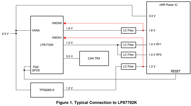
For LP87702K-Q1, 0x14 register shows the PG level including VMON1 threshold and window.

1. I will check VMON1 voltage tomorrow. (1.17-1.23V)

2. May you let me know the normal PG voltage if our pull high voltage is 3.3V with 1.8k pull-up resistor. Is it 3.3V or 1.2V?

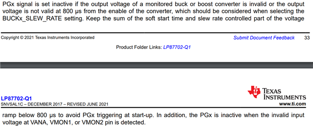
3. I don't understand the below part of datasheet. Does it mean that out VMON should ready no later 800us after enabling the LP87702K-Q1?
Do you have any suggestion that I need to check? Or can you share the common reason that PG0 doesn't work? Thank you.

Regards,

Roy

  • Hi Team,

    I check the VMON1 is 1.184V. Power sequence is showing as below.

    Green Buck0=VMON2 1.8V
    Orange VMON1 1.2V
    Yellow PG0  
    Blue VANA 3.3V

    Regards,

    Roy

  • Hi Roy,

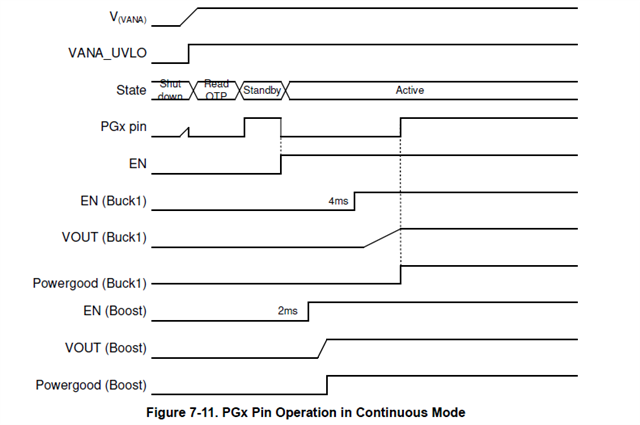
    Can you send me the schematic for this design so I can check the connections? The question 3 that you had is for gated mode of PG and in this LP87702K-Q1 the PG mode is set to continuous. The correct behavior for PG is shown in figure below

    PG0 in this device is monitoring VMON1, VMON2, VANA and BOOST so all these should be high. Can you check the boost voltage? 

    regards,

    Niko