This thread has been locked.

If you have a related question, please click the "Ask a related question" button in the top right corner. The newly created question will be automatically linked to this question.

UC3845A: DC/DC load regulation

Part Number: UC3845A
Other Parts Discussed in Thread: UC3845, UC3843, UC3842, , UC3843A

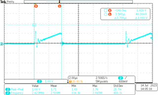
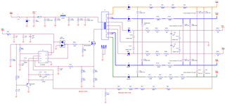
Non-isolated HV DC/DC (24VDC to 600VDC) with voltage closed loop control does not hold load. Output voltage starts dropping with increased load even though DC is about 43% (much lower than limit and primary current does not show any signs of saturation. Any suggestions? Thanks.

  • Hi. Are you using a boost converter, flyback? 

    Transient response:
    When you apply more load current, the output voltage will temporarily decrease due to the fact that the capacitor needs to provide more current suddenly and its voltage decreases. Also, the duty cycle will temporarily increase to provide more current to the secondary side.

    Steady State:
    At steady state, what will happen if you apply more load current, the duty cycle will remain with the same value because it just depends on input and output voltage. The case when max duty cycle of 50% will be reach is when there is a fast increased load current transient event. 

    Are you performing a load transient event? How is your load configuration? non-isolated means that you are not using a opto-isolator in your feedback loop? 

  • Hi Manuel,

    Thank you for looking into this issue. It is a flyback. I am referring to a gradual output voltage drop with load increase, not a transient response. Say, after some point further increase of output current by 10% causes voltage drop by 5% and more if I keep increasing load. There is no optocoupler there. Attenuated output voltage is fed to the feedback input of the controller. I expected better load regulation in this case. Switching frequency is about 100KHz. Attached is the voltage across the current sensing resistor in the source of the switching transistor. This is where I start seeing a problem.


    Currently resistor value is 0.3Ohm. I tried to reduce it by 35%. It improved the load regulation a bit, but not significantly. It is the right direction? As you can see from the waveform, average primary current is about 0.7A (3.33A peak at DC=42%). At 24V it comes to about 16Watt input. Output power is about 10.6Watt. Where am I loosing 5.4Watt? Transistor is rather cold (I would assume about 1Watt on it max). The controller is powered from a separate 15V supply. Stray capacitance in the secondary winding of the transformer looks large (spices of current).

    I do not understand Figure 7-5 in the datasheet if UC3845 has max DC 50%. I believe no matter what RtCt values DC is limited to 50%. Currently I have 2.2nF and 3.32K. According to the plot in Fig 7-5 max DC should be about 88%.

    It may be a good idea to increase a bit turn ratio Ns/Np to lower nominal DC.

    Would you recommend other newer controllers?

    Thank you.

  • Thanks for providing more information. I would suggest the next debug process:

    Debug process:
    - The controller is running out of power capability? Check the COMP pin and make sure it is not saturated at its limit (Vcc=+5V), make sure it is swinging to control and regulate the output voltage.
    -What is your maximum duty cycle? Check the RT/CT pin and check and measure the max duty cycle of your oscillator. If your duty cycle is not going higher than 43% it means that you would need to change your RT resistor and CT resistor to increase your max duty cycle and therefore improve your power capability.
    -What kind of compensation are you using? Is it a Integrator compensation? There is a capacitor connected between the FB and COMP pins? If not, you would be dealing with steady state error problem and the regulation is not appropriate.

    About Figure 7-5:
    This device UC3845 has a maximum duty cycle of 50%, the plot showed in Fig. 7-5 does not apply for this device. The reason why some of these devices have that duty cycle limit is because some isolated converters need to have a duty cycle lower than 50% to reset the transformer and volt-second balance the magnetizing inductance.

    About the sensed current picture:
    I do not see any issues with your primary current. The inductor will not saturate because the IC controls the peak current of the MOSFET. The high peaks at the beginning of the switching period is due to the parasitic capacitance at the switching node, which resonates with the inductance at high frequency.

  • To verify max duty cycle:

    In Section 8.3.6 of the datasheet you can check the equation to calculate Dmax (see attached). In Fig. 7.9 you can estimate you dead time depending on Cct. You might need to decrease Cct to decrease dead time and then increase Dmax. Note that in this case the switching frequency fs=fosc/2. If your fs=100KHz then fosc=200KHz and you can plug in this value in the equation. Also, note that decreasing Cct will increase fs (see attached).

  • Hello Manuel. Thank you for your explanations and suggestions. I will try increasing Rt to 6.8K and decreasing Ct to 1nF tomorrow. Also, I will double check the voltage waveform on COMP. Meanwhile, I just want to confirm that I do have capacitor 470pF between VFB and COMP. In parallel to this cap I have 100K and 10nF connected in series. I cannot find Figure 7.9 in the datasheet as you suggested. I am referring to UCx84xA Current-Mode PWM Controller datasheet (Rev. G) (ti.com)

    I suspect that the issue may be with insufficient Nsp for required output voltage of 630V. Operating duty cycle according to the formula 7 D=0.47 (Nps=0.03. Vin=24, Vout=634V. If this is the case and I cannot change the transformer at this stage, should I change to UC3842 or UC3843?

    Thanks,

  • Hi Bohdan. 
    Your feedback compensator values look good. You are using a Type II compensator to regulate output voltage and that should be good enough.
    I would first try to increase max duty cycle to 50% increasing RT and decreasing CT (to do not change fs as well). I recommend checking OSC pin to verify that.
    If that does not work, you might be running out of number of turns. You can change the IC to 3842 or 3843.

    Best!

  • Also, if possible I recommend using a BiCMOS device (UCC...) rather than a Bipolar (UC...). It provides lower current consumption, more accuracy and many other benefits (see attached.)

  • Thank you, Manuel.

    I just ordered 100% DC parts including UCC series. Will try tomorrow. What is the downside of using 100% DC part in my configuration?

    The circuit works well if I reduce the load and it holds the output voltage. Doesn't it an indication that turn ratio is still acceptable? I reduced output voltage to 560V (changed resistive attenuator), but it still does not hold output voltage if the load increases beyond about the same power level.

    Thanks,

  • Bohdan. You might need to decrease the value of your current sense resistor Rs. You need to design Rs value considering a maximum input voltage at the sense pin (see attached) of 1V when a peak current value is measured. If you design a higher Rs value than that, what would happen is that the comparator will be latching (turning off the CMOS) the PWM signal beforehand, and the IC will run out of power capability.

  • Hi Manuel.

    Reducing the current sensing resistor by 30% was the first thing I did, but, as I mentioned earlier, the effect was insufficient: I got 3% output voltage drop instead of 5% with the original current sensing resistor. It looks like there is a combination of few factors: current is hitting the limit, duty cycle is too close to the maximum. I will try both, smaller current sensing resistor and 100% duty cycle part. What is the risk of using 100% DC part in this topology?

    Thanks,

  • Hi Bohdan. 

    The "drawback" of using a duty cycle close to 100% is that is more difficult for the magnetizing indudctance of the flyback to reset. Also, the secondary current is higher and it woud lead to increase the output capacitance to be able to filter the ripple.Theoritically is possible but it would lead to more problemas. 

    In your case, accoordign to your specifications, you just need a duty cycle around 50%, so you shoudl be fine. 

  • Hello Manuel,

    I took me awhile to do more testing here. Increasing value of Rt from 3K32 to 7.5K and decreasing Ct from 2.2nF to 1nF really helped and the PS holds the output voltage at heavier load well, but I do not understand the mechanism here. See the waveform of the primary current attached.

    This time frequency is slightly lower 81kHz versus 96kHz but DC is now just 30% versus 42% before. Also, magically turn on spike is much lower while all parasitics remain the same. I would appreciate if you could comment on it, otherwise I am happy with the result and we can close the case. Thank you. 

  • Hi Bohdan. Your primary current looks great now. I think that the problem you were facing was a power capability issue. When the controller needs to provide more power than it can, the output voltage decreases to compensate that extra power that needs to provide, and the controllers runs at maximum duty cycle. Basically, the converter is running at its limits and that can also result in a harder switching (high peaks).

    Increasing your max duty cycle helped to alleviate that. Glad to have been able to help you. 

  • Thank you. All makes perfect sense. My confusion is that Nps=0.033 (3:90.5). Vout=635V, Vin=23V. Thus expected D=0.48 (formula 7 in the datasheet), not 30% as I am getting now. Also, I am using UC3845A which has D limited to 50% and I thought that plot 7-5 in the datasheet did not apply and Rt did not affect max duty cycle. Did I misunderstand anything here?

    Thanks

  • Hi Bohdan. Equation 7 in the datasheet is to calculate duty cycle in Continuous Conduction Mode (CCM). Your Flyback is working in Discontinuous Conduction Mode (DCM). You need to apply volt-second balance to the primary inductor and charge balance to the output cap to get the equation of the duty cycle for DCM. Here is the equation:

    For a resistor load: D=sqrt(2*fs*L/Rload)*Vout/Vin

    For an electronic load: D=sqrt(2*fs*L*Vout*Iload)/Vin

  • Hi Manuel,

    I am sorry for taking so much of your time, but I am rather confused with the oscillator circuitry. Increasing Rt helped initially to handle about 12Watt of output power with reasonable switching current as you saw above and voltage on COMP pin about 1VDC. When I added another 2Watt of load, COMP went up to about 4V. Further small increase caused COMP voltage heating 5V. Increasing Rt to 10kOHM and Ct=1nF helped, but frequency dropped to about 60kHz. Formula in Figure 7-6 suggests 86kHz!

    Thanks,

  • Hi Bohdan.

    Check again the values of Rt and CT. There is a considerable difference between 60 and 86 KHz. It might be that your Ct cap is taking more than expected time to charge/discharge. Try a new cap and connect it as close as possible to the IC pins.

  • Hi Manuel,

    Thank you very much for all your suggestions. I verified/replaced Rt/Ct, tried different ICs including UC3843A, but oscillation frequency remained lower than expected - please have a look at the results in the attached spreadsheet. 

    HVPS_UC3845A.xlsx

    Then I realized that in this design there was 390pF capacitor between Rt/Ct and I_SNS which explained the issue. It is an old design done by my predecessors and I need to get more power out of it. I overlooked this capacitor. I would appreciate if you could take a look at the attached schematic and tell me what function of this cap is. By the way, you are right, layout is not great and Rt/Ct are not close to pin 4 as well as some other things. I will try to fix it.

    I observed that once I started loading more +/-315V windings, the larger current spikes are on turn on. And now relatively small increase of output power causes a rapid increase of temperature in both transformer and switching transistor. Do you believe it could be improved somehow?


    Thank you for your patience.

  • Hi Bohdan. 

    The reason why a capacitor in series with a resistor is connected between RT/CT and I_SNS pins is to add slope compensation for the peak current mode control. Slope compensation is necessary when the controllers need to work at duty cycles higher than 50%. UC3845 will never work at duty cycles higher than 50%, so no need for slope compensation. You can remove that capacitor and verify your switching frequency. That capacitor is likely the reason why your fs is lower than expected.

  • Hi Manuel,

    Thank you very much. In my case I had no resistor in series with the capacitor between RT/CT and I_SNS pins and when I removed it all became reasonable: frequency is much closer to the expected value and most importantly the spikes on turn on reduced noticeably, especially when I added 2.4Watt of load. The transformer and transistor are much cooler now. At 13Watt of load the spikes are larger than at 15.4Watt. Less heat at larger load too. I have no explanation for it but it is a great result. See the last two columns in the attached spreadsheet.

    Thank you.4540.HVPS_UC3845A.xlsx