Because of the Thanksgiving holiday in the U.S., TI E2E™ design support forum responses may be delayed from November 25 through December 2. Thank you for your patience.

This thread has been locked.

If you have a related question, please click the "Ask a related question" button in the top right corner. The newly created question will be automatically linked to this question.

UCC28019: UCC28019

Part Number: UCC28019

Hi all,

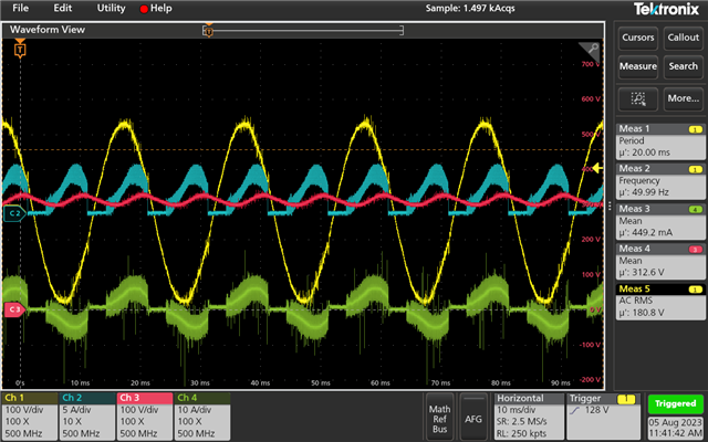
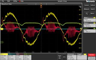
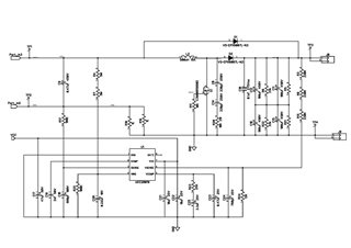
I am implementing a PFC boost using UCC28019. The load is around 800W. Though the voltage is reaching 400V. The input current is having distortion. Please can you suggest what is to be done to resolve this. I am attaching the schematic and the waveforms
  • Hi Sachin,

    Thank you for the query on UCC28019.

    1. The sense resistor seems wrong for 800W. Calculations show around 30mohm, but schematic shows wrong value.

    2. The voltage needs tuning. Please refer attached excel.

    3. Output cap needs to be increased.

    Please let us know if you have any questions and know your observations after making these changes.

    Regards,

    Harish

    3404.sluc069e.xlsx

  • I changed the values of components as shown in new schematic. Thoug there is slight improve ment in current,  there is no Voltage regulation. I am unable to connect probes to Vcomp and Icomp pins as it immediatley affects the system output even when slowly increasing the output through variac. 

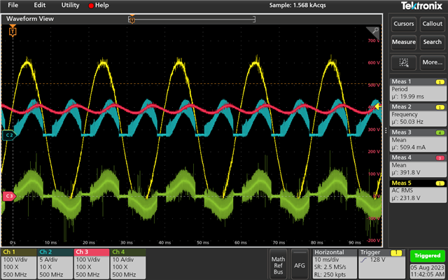
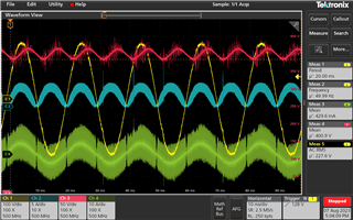
    The yellow signal (input Voltage),Blue signal (inductor current), Green Signal (Input current), Red Signal (Output Voltage).

    What could be done to improve the control process. and what is procedure for compensator tuning in hardware.

  • Hi Sachin

    Please refer to page33 to 40 of the schematic which gives detailed procedure on compensator design.

    Also I still see the schematic shows worng compensation values to what is suggested by the excel calculator I attached. Please use recommended values.

    Thank you

    Regards,

    Harish

  • Hi Harish, 

    Thanks. Now the system is running. Is the noise in the input current (Green Waveform) due to probe ( I am using 70kHz Bandwidth Clamp probe from Keysight). What can be done to reduce the noise.

    The compensator values actually used is

    Cvsense=C24

    1000pf

    Cicomp=C19

    1000pf

    Cvcomp=C25

    10uF

    Rvcomp=R23

    13k

    Cvcomp=C23

    1uF

    Rvins2=R25

    100k

    Cvins=C20

    33,000pF

    Rfb2=R24

    12.5k

    Regards

  • Hi Sachin,

    The signals look good from the initial waveforms shared. Try checking with BW limit on too. It could be due to probe pick up as well due to big loop (due to clamp type probe)

    The following series of curent probes should be good and if you are using anything close to this it should be ok to probe current

    https://prc.keysight.com/Content/PDF_Files/5989-6432EN.pdf

    Regards,

    Harish 

  • Hi Harish,

    Most of the issues have been resolved.

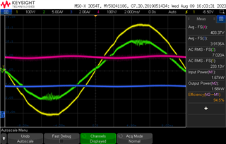
    However, when I increased the load to 1600W. The system works in steady state, but there is distortion in current peaks. Is this due to inductor saturation or compensator issue. The current sensor is 0.025 (as suggested in excel, with startup voltage around 125V)

    When I tried to switch on instantly, the Current Sense resistor and RVINS resistors and IC got damaged. What can be done to increase soft start. Presently I am turning on bias supply separately. And then turning on the Input Supply.

    Also the PF is around 0.97, what can be done to increase the PF around 0.99. Is it due to impedance of auto-transformer used for manually increasing the input voltage.

  • Hi Sachin,

    Sense resistor has to be chosen for the power level for which your system is designed for. Intiallly you informed 800W and the value which you used seemed fine. But now you say 1600W, definitely you will have to reduce sense resistor to 0.014 ohm and it is easily evident by feeding this value into the tool. Hence your current is clamped. 

    There is a startup sequence for PFC. Typically you turn on AC input voltage, turn on inrush current limiting relays and finally turn on the controller. Please ensure there is proper power sequencing else you will end with damage.

    Regards,

    Harish

  • Hi Harish, 

    Thanks for your reply. Can you give me any reference for Inrush current limiting relays or is NTC enough for this. I thought the current sense resistor value obtained in the excel tool is due to the startup voltage. If we increase the startup voltage to 150V, the sense resistor recommended comes to 0.025. So did not think Rsense should be not be issue at 230V