This thread has been locked.

If you have a related question, please click the "Ask a related question" button in the top right corner. The newly created question will be automatically linked to this question.

LM76003: Definition of EN rising and PG rising

Part Number: LM76003
Other Parts Discussed in Thread: LM76002,

Hi team,

My customer is asking about the tss (soft start time.)

The definition is "CSS = OPEN, from EN rising edge to PGOOD rising edge"

In the datasheet,  EN rising is defined as:

, and PGOOD rising is defined as:

 .

The power good does not talk about the timing.


With that said, how would you define the soft start time?

My understanding is the time between "the EN reaches 1.2V" and "PGOOD reaches 50% of the defined voltage (Vcc/2)".

Please let me know.


Thanks,

Luke

  • Hi Luke,

    Datasheet mentioned "The LM76002/LM76003 employs the internal soft-start control ramp and starts up to the regulated output voltage in 6.3 ms typically." It refers to the time  between "EN reaches 1.2V" and "PGOOD reaches 90% of the defined voltage". 

    Regards,

    Hongjia

  • Hi Hongjia

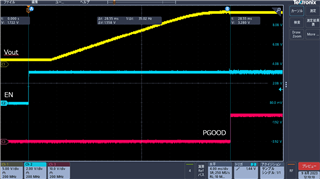
    Sorry for cutting in,I have measured each signal such as Enable, PGOOD, and Vout.

    Our set is below

    sync : High(FPWM mode)

    Css : 0.047uF(typ)

    tss : 23.5msec(typ)

    Load : No Load

    as a result of measurement, tss (= 28.55msec) was not as set.

    (Even allowing for variations in Css and Iss, this value is a bit large)

    I have a few questions about this result.

    Could you please reply to my question.

    ・Why don't the measured result and setting match ?

    ・Why is there a delay in the start of Vout output relative to enable?

     I think the tss setting is not EN to PGOOD, but the time from the beginning of the rise of Vout to PGOOD.

    Could you please reconfirm the definition of tss once again?

    Regards

    Taki

  • Hi Taki,

    The time below constitutes the delay between EN goes high and Vo starts increasing:

    1. IC configuration time: this is the time between EN goes high and SS starts increasing. (including VCC cap charged up past VCC_UVLO, bootstrap cap charged up past BOOT UVLO)

    2. Charge time for SS offset voltage. SS should accumulate some voltage before the error amplifier can output current to source into internal COMP. 

    Can you also capture SS to see when SS starts increasing? I will also check on our EVM and let you know.

    Regards,

    Hongjia

  • Hi Takin,

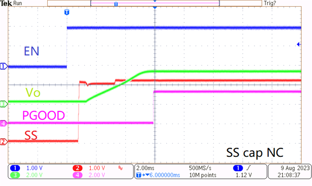
    Please find the EVM test results below. Image1: SS cap NC. SS time=~6ms, from EN high to PG high. Image2: SS cap=22nF, SS time=11ms, from SS=0 to SS=VREF=1V. 

    Regards,

    Hongjia

  • Hi Hongjia

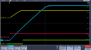
    I have measured again, and I found that time between SS=0 and SS=VREF=1V is about 24msec.

    But why does the definition of tss SS=0 to SS=VREF=1V?

    Could you tell me the relationship between SS=VREF and Vout.

    When using this IC, is it necessary to check the SS waveform to verify that the tss result are as set?

  • Hi Takin,

    You can refer to Page 12 Block diagram to see that both SS and VREF are fed into the internal error amplifier and the one with smaller value serves as the real reference. When SS is smaller than VREF, SS is the actual reference and Vo follows SS to ramp up, and this is the so-called soft start. That's why SS is defined as the time from SS=0 to SS=VREF. 

    When using this device, you don't need to check if SS is as set. Both my and your test results show that it is exactly the same as what we set.

    Hope it clarifies.

    Regards,

    Hongjia