This thread has been locked.

If you have a related question, please click the "Ask a related question" button in the top right corner. The newly created question will be automatically linked to this question.

UC1901-SP: Avoiding the 2.5V Feedback Offset in Reference Design UC1843BEVM-CVAL

Part Number: UC1901-SP
Other Parts Discussed in Thread: UC1843BEVM-CVAL, UC1901, UC1843-SP, UC1843, UC1843B-SP

Hello,

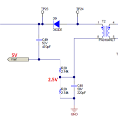
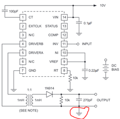
I am designing a power supply using the UC1901-SP for isolated feedback.  In the reference design for the 'UC1843BEVM-CVAL' eval board, a 2.5V offset it added to the feedback signal by using the UC1843B's 5V reference and dividing it down using two 2.74k resistors:


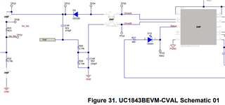
My understanding is this 2.5V offset is needed because the UC1843B uses a 2.5V reference for its feedback and the UC1901-SP output capability is limited to 1.5V max.  Is this correct?

If I want to simplify my circuit and avoid the need for a 2.5V offset, can I use a 1:2 transformer instead in order to increase the range to 3.0V (2 x 1.5V), so that I exceed the 2.5V reference? If so, any drawbacks?

If I decide to not use the UC1843B and instead use a controller with a 1.2V reference, can I do away with the offset and connect the feedback signal (post-diode) to my controller?

Thanks!

  • Hey Vince,

    Im a bit confused about what you are asking about.

    The UC1901 is used in TIDA070002 and is not used in the UC1843B EVM.

    Some sort of way of injecting the error voltage from the UC1901 is needed if it is being used.

    Our best suggeation is actually to inject it across a capacitor in line with a resistor dividor to the controller voltage reference that is being pulled from something like a 5 V rail

    Thanks,

    Daniel

  • Hi Daniel,

    Thanks for the quick reply and feedback.  You're right, it looks like the TIDA070002 schematic is an updated revision of the UC1843BEVM-CVAL .  I'll use the TIDA070002 moving forward as a reference.

    My earlier questions were an attempt to understand why the feedback circuit was using a 2.74k+2.74k resistor divider network:

    I want to guess the 2.5V offset is needed because the controller 5962P8670409VYC (UC1843-SP) is using a 2.5V reference voltage for its feedback loop, but with a 1:1 transformer the UC1901 can only support 1.5V?  

    To your suggestion:

    inject it across a capacitor in line with a resistor dividor to the controller voltage reference that is being pulled from something like a 5 V rail

    Is the capacitor you are referring to C49 in the schematic?  The above circuit AC couples the error signal into 5Vref + offsets the signal by 2.5V?


    If I wanted to simplify the feedback circuit, can I instead just use a 2:1 transformer?  This adds a gain of 2x to the error signal, and allows it to reach the 2.5V feedback reference voltage of the UC1843:


    I found in the UC1901 app note that a higher turns ratio may be needed if my reference voltage is greater than 1V:
    "The UC1901 is specified to generate maximum carrier levels equal to or in excess of 1.6V peak. This indicates that a turns ratio of greater than one-to-one will be required for the coupling transformer if the detector output must exceed approximately 1V, (allowing for a detector diode drop of 0.6V)."
    However, I wanted to verify with you if there are any drawbacks to this approach that I am not considering.

    Thanks for the help Daniel! 

    Regards,
    Vince


  • Hey Vince,

    The capacitor I am talking about would be in series with R23, similar to how it is in the UC1901-SP datasheet, where instead of a ground you would place a resistor divider and have the top of the output connected to 5 V.

    The thing you are not considering in using a 2:1 transformer is the device uses amplitude modulation.
    In amplitude modulation the error voltage will go from 0 V to the max swing (lets say 1.7 V)

    If you try and use only the max part of the swing to run your device, you end up with very little range that the UC1901-SP will use when representing the error voltage.

    Placing the offset allows for the UC1901-SP to use more of the range to represent the error signal.

    Thanks,
    Daniel

  • Hi Daniel,

    Thank you for clarifying on all those points, I've implemented your suggestions in my schematic and have added a BOM stuffing option for a series capacitor in-line with the feedback divider R23 and R32.

    Two final questions:

    - I understand the 50ohm R23 is likely used for frequency response measurements, but what is the purpose of R32 9.76k?   Since the 50ohm R23 is very small compared to R32, it is a weak voltage divider of the isolated signal.


    - What is the purpose of the D7,R8,C43,Q2 circuit tied to the COMP pin?


    Thanks!

    Regards,
    Vince

  • Hey Vince,

    The 9.76 kOhm was just to pull current out of the transformer as a burden resistor.
    I don't believe its required in the form I suggested to implement the UC1901-SP.

    Thanks,
    Daniel

  • Hey Vince,

    Apologies I only answered 1 question.

    That circuit was a rudimentary soft start to add to the UC1843B-SP.
    Depending on your controller it may not be required.

    Thanks,
    Daniel