This thread has been locked.

If you have a related question, please click the "Ask a related question" button in the top right corner. The newly created question will be automatically linked to this question.

LM61480-Q1: inverting output not functioning

Part Number: LM61480-Q1
Other Parts Discussed in Thread: LM61480, LM61495RPHEVM, LM61495

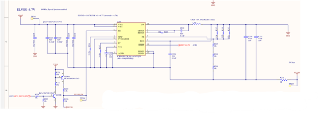
We have implemented the LM61480 as an inverting buck controller.   20V input  with -4.7V output as shown in the attached picture.    The positive output version (4.6V)  works as expected.

The inverting supply  output is  -20V when enabled..    VCC = ~-15.7V  FB = -14.6V.  ELVSS = ~-3.8V when enabled.  PGOOD (Reset) = 0V  measurments are to GND (not ELVSS)

Any thoughts on what is incorrect?  We have tried changing the feedback registers with some success.  Was able to get to -6V output, but any lower (Rfb=320K, Rfbt=110.7K) caused an unrecoverable short.

  • Hi,

    Have you tried looking into the app note that details the process to configure buck to IBB (https://www.ti.com/lit/an/snva856b/snva856b.pdf)? 

    Also the current feedback resistors I see are: Rtop_effective = 11kOhm, Rbottom_effective = 30kOhm. 

    If you wanted a 4.7V output, you should be able to achieve it with Rtop = 100kOhm and Rbottom = 31.2kOhm. Have you tried using just a singe top and bottom resistor for the 4.7V output?

    Regards,

    Jimmy 

  • Hi Jimmy,

    Yes I have consulted all the IBB app notes I can find  from TI as well as other vendors.   I've also created an IBB before using another TI component  which worked as expected right at startup.  though it was a simpler device without sync or spsp.  Though not sure if that matters.  I'm hoping I missed something obvious in this design.

    Rtop_effective should be ~110K  (332K//332k//332k),  or did I miss something that makes the result be 11k?

    Your calculation  of 100k/31.2k+1 = 4.2V,   is the other 0.5V made up by an internal diode drop?   From the document you referenced the inverted output feedback resistors match the formulas for the non-inverted mode. Unless the LM61480 is different the formula should be Vout = Rfbt/Rfbb+1.  With Vref = 1V.  So it's curious that the FB pin is measuring ~-14.6V,  I would expect it to be 1V higher than the output.

    I  considered that the Rfbb and Rfbt had to be swapped but that caused an apparently destructive result,  which is curious.

    Yes we have simplified the resistors to use a single resistor (RFbt=110k, Rfbb=30K)  with the same -19V result.

    It seems there is something specific to the LM61480, but I don't see what it could be.

  • Hi,

    Apologies I misread the top resistor as 33kOhm. Looking at it closely it is 332kOhm which 3 in parallel would be around 110k as you mentioned. In that case then it is very odd since the effective top of 110k and bottom of 30k should result in 4.6V per the equation formula. 

    While I look into the schematic in more detail, can you provide your PCB layout and/or top view image of your system board? 

    Also is this a new design or an old design? I have not had any customers with issues using this device in converted for IBB so this is definitely a first.

    Can you give me a block diagram of your test setup (input power supply, IC, and downstream loading circuit if any)? 

    Regards,

    Jimmy 

  • Hi Jimmy,

    Attached is a layout image of the IBB LM61480.   Not sure how useful this is but you should be able to see that we followed the

    recommended layout as closely as is possible, with the changes

    the system currently is very simple -  Bench supply 20V ->Vin LM61480.   A 3.3V rail is also enabled on the board which powers the LM61480 ENable through the level-shift circuit.   Currently the only load is a TI TPS72301DDCR  which is not enabled.

    This is a new design. First experience with the LM61480.   As mentioned earlier there is also a positive supply using the LM61480, this is functioning as expected.

    I have done some further testing and found the FB is -4.00V (according to my cheap DMM)  So I changed the FB resistors,  So Rfbb=929K (instead of 30K),  Rfbt=110k (no change) ,  output is now -4.7V as desired. 

    When we tried making a similar change earlier (600k for Rfbb) a dead-short appeared, seemingly destroying the IC.  The above board that appears to be working currently has BIAS floating,  not sure if that is allowing operation.

    I think the question now is why does the FB pin work at 4V,  it should be 1V.   I can't imagine a mistake in the schematic that would cause this. 

    Regards,

    Roy

  • Hi Roy,

    That is even more interesting that keeping the resistor ratio the same but changing the resistor values to 929kOhm top and 110kOhm bottom results in -4.7V output. This does not fall in line with the output voltage equation and reference voltage being 1V. 

    May I ask how many boards experience this issue and if you can replicate the same problem on another "fresh" board. There is nothing in the schematic that would suggest there is an issue with output voltage regulating to -4.7V so I am suspecting there is something on your actual board. Though the PCB layout (specifically SW node connection) is not optimal, there is nothing in particular that I could pinpoint as being the root cause of this failure.

    Can you confirm if you've tested on another fresh board and see the exact same output voltage regulation issue even with Rtop_effective of 110kOhm and Rbottom_effective of 30kOhm? 

    Regards.

    Jimmy

  • Hi Jimmy,

    I'm on my 4th board or testing.   3 destroyed LM61480's so far. 

    I tried isolating the BIAS pin and tying it to output (PGND pin)  instead of system GND.   This appeared to work for a short bit but after probing some pins to verify the voltages the IC shorted out.  Not sure if probing or time caused the short.

    You indicated other customers have the LM61480 working in IBB mode.  Are there any posts or other information you could point me to?  maybe I can see something that is different.

    Regards

    Roy

  • Hi Roy,

    Apologies for not being able to get back to you since the E2E forum was on maintenance these last few days. 

    I had directly contact your sales support (Brian Berner) but I also want to reiterate the question here:

    Can you make sure that when you are probing the device, all the probes are referenced to the IC return (negative output voltage rail).

    From experience I have blown up ICs in IBB configuring from accidentally connecting the wrong returns to the probe since my oscilloscope’s probe return on all 4 channels are connected together.

    In my case I was measuring VIN (referenced to GND) and measuring SW (referenced to negative output rail) and that blew up my IC in the past.

    It sounds like the device was operating for some time before the probing which I am suspecting is causing this issue. 

    Regards,

    Jimmy

  • After extensive debugging we have determined that the FB loop is 'defective' .   The FB loop is either variable between 2V and 4V or stable at 4V,  it is never 1V as expected. All other I/O on the LM61480 shows the expected values (VCC=3.3V, Cboot = ~2V above Vin)   Unclear if the parts we have are somehow damaged or if something else is going on  (does not appear to be board soldering issue)

    Switching to a different device as we can not determine the root cause

  • Hi Roy,

    If it make sense, I can configure a LM61495RPHEVM for IBB operation using similar components as what is shown in your schematic. Test that it is regulating to -4.7V and ship it to you for further evaluation of the LM61495. 

    Please let me know if this is something you and your team would be interested in. 

    Regards,

    Jimmy