


One commonly misunderstood topic regarding low dropout regulators (LDOs) is thermal dissipation. LDOs drop the input voltage using a FET in order to achieve the desired output rail. This power dissipates across the LDO and energy releases in an exothermic reaction. The larger the voltage differential the greater the thermal dissipation. In order to mitigate thermal-related issues, it is important to choose both the correct part and package (for more information on picking the right package please see LDO basics ). Once the part is chosen there are still multiple ways that thermal dissipation can be improved. A good board layout can improve thermal dissipation by 30-50% from the JEDEC specified by R_θJA. Similarly, a bad layout can significantly degrade the IC’s ability to dissipate heat. Good board practices include: adding additional metal and thermal vias around hot IC components whenever possible. For additional board improvements, please see an empirical analysis of the impact of board layout on LDO thermal performance. Below we will discuss common issues and questions in regards to thermals.
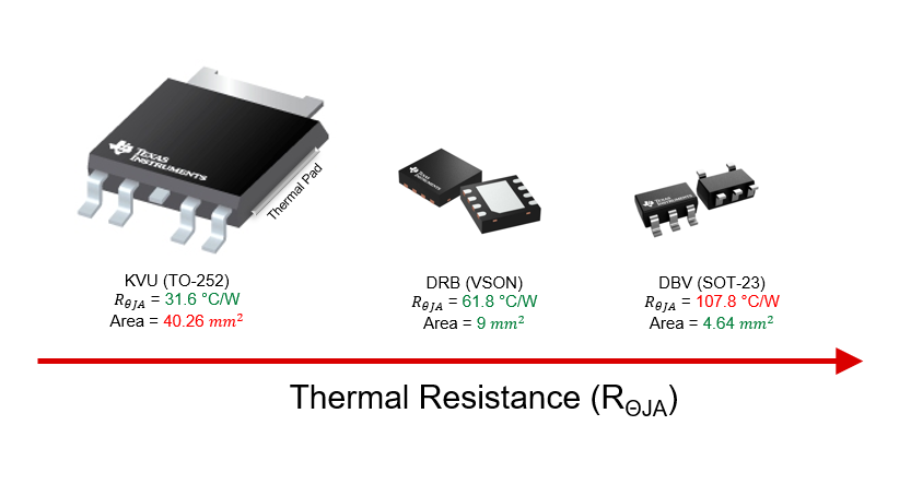
Figure 1: Size and thermal efficiency of the KVU, DRB, and DBV packages. The thermal resistance value specifies how many degrees Celsius the IC junction temperature will raise per one Watt of power dissipated. Generally speaking the larger the package, the better thermal dissipation (especially if it has a thermal pad).
Common Questions Explored Below:
1) How are thermals metrics calculated in Texas Instruments datasheets?
2) Thermal metrics R_θJA,T_J,and T_A defined.
3) What are the differences in the thermal metrics provided in the datasheet and what are their practical uses?
4) How much will thermal metrics vary based on the board?
5) Why do different parts in the same packages have different thermal values when comparing different metrics? Similarly, when comparing two different packages, why does one have a better R_θJA, but a worse R_(θJC(top)) value?
6) How can thermals be tested in the lab?
7) How do I calculate the temperature of my device?
8) What is the best metric to compare thermals across devices?
9) How can one compare thermal specifications between TI and non-TI devices?
Additional Resources and References provided down below.
Common Questions:
1) How are thermal metrics calculated in Texas Instruments datasheets?
Texas Instruments datasheets use thermal simulations and models based on the JEDEC high-K standard board layout (defined by JESD51-7) to calculate the metrics. These simulations are verified with rigorous real-world measurements to verify modeling parameters are well correlated. For more information on the JEDEC board please see Semiconductor and IC Package Thermal Metrics. For a comparison between different board designs and the JEDEC standard please see an empirical analysis of the impact of board layout on LDO thermal performance.

Figure 2: JEDEC Standard 2s2p PCB.
Image sourced from TPS7B86-Q1 datasheet.
2) Thermal metrics R_θJA,T_J,and T_A defined.
R_θJA is defined by how many degrees Celsius the IC’s junction temperature (T_J) will raise relative to the ambient temperature (T_A) per one Watt of power dissipation. For example, an R_θJA value of 61.8 °C/W means that the IC’s temperature will raise 61.8 degrees above the ambient temperature for every Watt of power dissipated.
3) What are the differences in the thermal metrics provided in the datasheet and what are their practical uses?
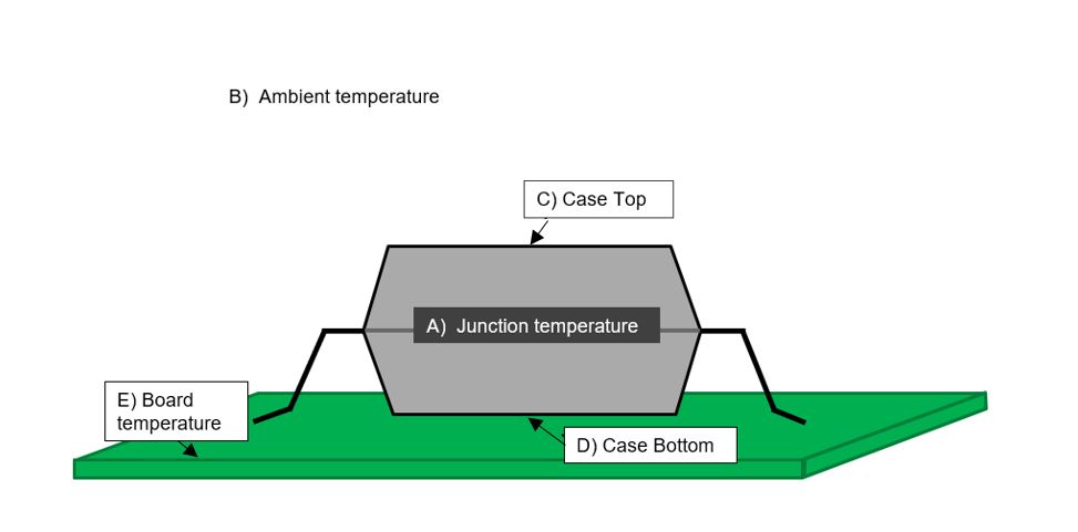
Figure 3: Diagram of thermal metric key terms, below each of these are explained and which thermal metric corresponds.
Table 1: Thermal Metrics Explained
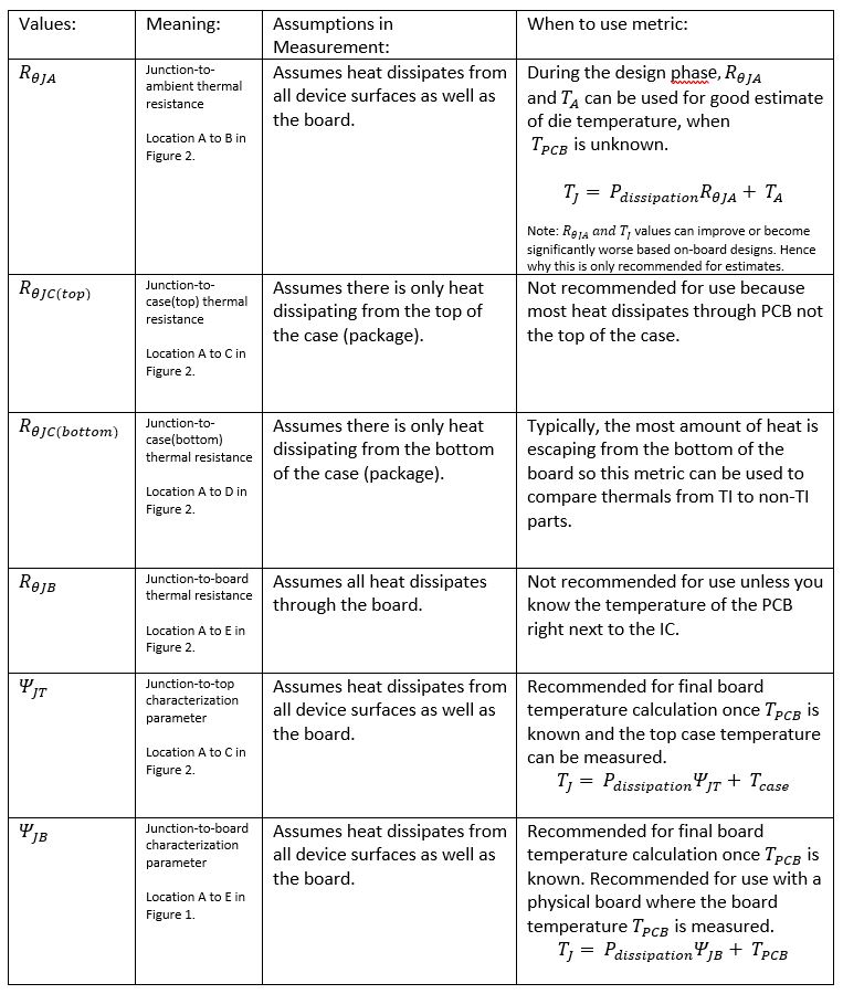
Generally, psi board measurements tend to provide a more accurate approximation in comparison to the theta metrics. This is due to the psi values in the JEDEC standard not assuming that thermals are coming from one location, but from multiple locations including the IC and the board.
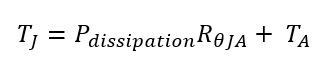
The best way to calculate junction temperature is using the equation below.
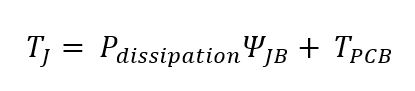
This adds complication because the T_PCB usually is not known until the board is laid out, parts are chosen, and the PCB has been fabricated. This is one of the key reasons the R_θJA values are still commonly used for estimating junction temperature during the design phase. Before the board temperature can be known the ambient temperature of the air is usually known by designers and can be used to calculate the junction temperature of an IC.
Please note this is an approximation which is strongly affected by the PCB board layout. For more information on how R_θJA will be affected by PCB layout see question #4.
For more information on these metrics and details refer to Semiconductor and IC Package Thermal Metrics.
4) How much will thermal metrics vary based on the board design?
It has been shown that board design can improve thermal performance by about 30-50% compared to the JEDEC High-K board standard. An empirical analysis of the impact of board layout on LDO thermal performance provides an in-depth analysis comparing the R_θJA for three different packages across five unique layouts. To summarize one example of board differences, Figure 7 in the report (shown below) shows the comparison of the different board design using the TPS745 (WSON) part 2x2 in package which has a JEDEC standard simulated value of R_θJA= 80.3°C/W. This shows a 46% improvement is possible using thermally saturated board and a 42% improvement using the thermally enhanced board (please see the App Note for more information on these layout differences). However, against a thermally inefficient single layer board (1S0P), thermal performance degrades significantly, increasing 210%. This stresses the importance of using good layout practices and adding metal and thermal vias around hot components whenever possible.
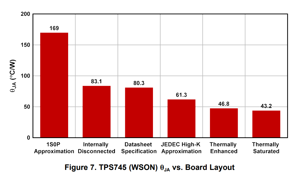
Source of figure and data from: An empirical analysis of the impact of board layout on LDO thermal performance.
5) A) Why do different parts in the same packages have different thermal values when comparing different metrics? B) Similarly, when comparing two different packages, why does one have a better R_θJA, but a worse R_(θJC(top)) value?
A) When looking at different packages, a device could have an improved thermal pad design but have more mold compound between the top of the die and the top of the package. This may result in a lower R_θJA and a higher R_(θJC(top)) (recall that R_(θJC(top)) thermal resistance assumes all the heat is transferred through the top of the case, which is a bad assumption).
B) R_θJA & R_(θJC(top)) values are greatly dependent on die size, thermal pad of the package, and the die’s vertical (z location) within the mold compound. The most effective path for removing heat is usually a thermal pad which is a slug of metal on the bottom of the package soldered to the PCB. A thermal pad allows the entire surface area of the die to more efficiently conduct heat to the PCB which lowers junction temperature and lowers R_θJA.
6) How can thermals be tested in the lab?
Thermals can be tested in the lab using the linear relationship between junction temperature and power dissipation. As power dissipation rises the junction temperature of the die also rises in a linear fashion. By using this phenomenon, you can measure R_θJA for your particular board. In order to measure an accurate T_A (ambient temperature) a ThermoStream or oven can be used to set and measure the air temperature around the LDO. For high accuracy measurements use a well-insulated oven and a temperature probe in the chamber, R_θJA is defined with only natural convection (no forced air). In the below equation there are two unknown values: T_J (junction temperature) and R_θJA.
Two equations will be needed to solve for the unknowns. T_A and P_dissipation will need to be manipulated to get device into thermal shutdown which occurs at a repeatable temperature for the tested unit. A relatively high value for T_A should be chosen, then the P_dissipation can be increased until the device goes into thermal shutdown. Data points will need to be recorded when the LDO goes into thermal shutdown to get an accurate measurement. After changing T_A or P_dissipation wait a few minutes before proceeding to the next measurement point in order to allow the device and PCB temperatures to stabilize. Keep in mind some test equipment may stop working at high temperatures so choose accordingly. The following procedure was used to test the TO-252 package. The test conditions will significantly vary based on package, to speed up measurement test conditions should be chosen close to the estimated thermal shutdown.
Equation 1: use to calculate Junction Temperature
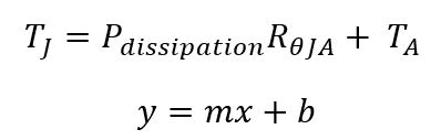
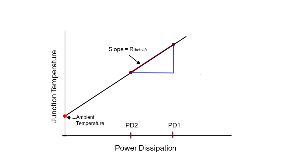
Figure 4: Visual representation of the linear relationship between junction temperature and power dissipation.
For example:
Measurement 1: Set the oven to 125°C. Using a 5V output LDO with a 300mA load, start the Vin (input voltage) at 20V (this value is chosen by the user) and increase the voltage very slowly until the device goes into thermal shutdown (the device will turn off) with a fixed device of 12V for the output voltage. Iout was measured and equal to 0.293A. Once the device goes into thermal shutdown record input voltage of the device.
Vin = 25.02 V, Vout = 5.0V, Iout = 0.293A, Temp = 125°C – started voltage at 23.0V and increase by 0.02 until the device went into thermal shutdown at 25.02 V.
These values are then used to create this equation:
![]()
Measurement 2: Vin = 15.80 V, Vout = 5V, Iout = 0.283A, Temp = 150°C – started voltage at 12.0 V and increase by 0.02 until the device went into thermal shutdown at 15.08 V.
![]()
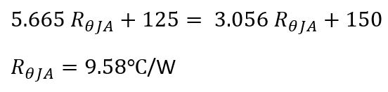
We can set these equations equal to each other because the thermal shutdown occurs at the same junction temperature:
For additional help and resources on calculations please see Video Training: Measuring Thermals - How Hot is Your LDO?
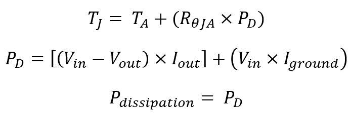
7) How do I calculate the temperature of my device?
Below are the equations needed for calculating the junction temperature (TJ) when the ambient temperature is known (TA). Note, I_ground is found in TI datasheets but for load currents above 1mA, the additional power dissipation caused by the ground current (Iground) will be small enough that it can likely be ignored. R_θJA value can be used from calculation above or for an initial estimate the datasheet number can be used.
8) What is the best metric to compare thermals across devices?
A: When deciding between two devices with thermal pads the best metric to compare is
R_(θJC(bottom)) or Junction-to-case(bottom) thermal resistance. Usually a large majority of the heat from the LDO is escaping through the bottom thermal so R_(θJC(bottom)) is the best metric to compare two different devices because it removes any PCB board assumptions various manufacturers may have made when providing other thermal metrics. For devices without a thermal pad, Ψ_JB is the best metric to compare since most of the heat is still transferred to the PCB through the pins.
9) How can one compare thermal specifications between TI and non-TI devices?
A: Use metrics explained above in question #8. Additionally, always check and compare thermal test conditions against two different brands devices. If test conditions are vague or do not provide much information on how they are taken, it is not safe to assume they used the JEDEC standard board for simulations. Additionally, check to see if the their board meets the standard JEDEC specifications and ensure they did not add additional copper, additional layers, etc. to their design. If both companies are using the same board assumptions then the metrics provide a direct comparison. If the PCB assumptions are not the same then a direct comparison of the values cannot be made and should be tested on the same board; this is due to the large effect that board layout can have on thermal performance.
Additional Resources and References:
Video Training LDO thermal basics – video version of LDO thermal basics
LDO basics – basic explanation of LDO and overview of some common issues and topics
An empirical analysis of the impact of board layout on LDO thermal performance – In-depth thermal comparison between five different board layout and design
Semiconductor and IC Package Thermal Metrics – In-depth explanation of JEDEC stand thermal metrics
LDOs Thermal Performance in Small SMD Packages – compares continuous-load-condition and pulsed-load-condition
Video Training: Measuring Thermals - How Hot is Your LDO? – video guide on how to measure IC thermals and goes through thermal equations and method mentioned above.