This thread has been locked.

If you have a related question, please click the "Ask a related question" button in the top right corner. The newly created question will be automatically linked to this question.

UCC27624: Pin2 and Pin4 operate question

Part Number: UCC27624

Hi Expert,

My customer wonder to know UCCS7624's pin2 and pin4 detail info as below;

  1. I want to know the max. input current of the Pin2 and Pin4 ( in other means INA and INB)
  2. Are there any requirements for the rise rate of the PIN2 and PIN4 input signal?
  3. Is it recommended to design RC circuits for Pin2 and Pin4 input signals?

Eddie

  • Hi Eddie,

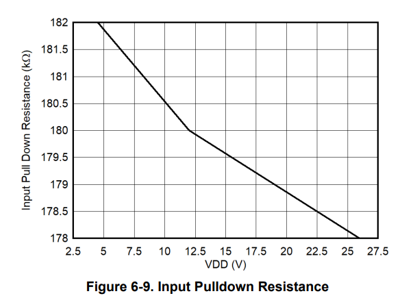
    1. The input pin current can be found by dividing the input voltage with the input pulldown resistance. The resistance is based on the VDD supplied (plot shown below), so to find the max input current, divide max recommended input voltage (26V) with whatever the resistance is.

    2. If you mean slew rate of the signal, the device's input pins can handle a very wide range of slew rates. If you're using a microcontroller to drive the input signal, then the rate should be fast enough to not cause a concern. Please let me know if this answers your question properly.

    3. There's usually high frequency noise associated with the signal frequency (~10 MHz noise on ~100 kHz signal), so we do recommend designing an RC filter for the input pins to filter out the noise. Make sure to place the filter as close to the input pins as possible to reduce unnecessary inductance.

    Thanks,

    Rubas