This thread has been locked.

If you have a related question, please click the "Ask a related question" button in the top right corner. The newly created question will be automatically linked to this question.

BQ25703A: shipping mode

Part Number: BQ25703A
Other Parts Discussed in Thread: BQ25703, , BQSTUDIO

HI

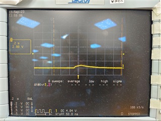
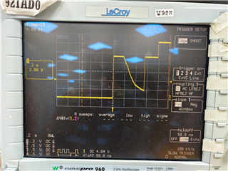
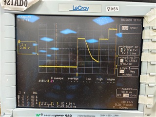
A customer has a question about setting the battery to enter shipping mode. Generally, the battery only needs to be supplied with a certain voltage (the current can be very small) to wake it up. Currently, after our battery enters shipping mode, the voltage of the BQ25703 Charger jumps up to about 1V and then quickly drops to about 0V after the adapter is inserted, so the battery will not wake up. What protection mechanism does BQ25703 have to prevent the voltage at the battery end from outputting?

  • Hello Gareth,

    I need more information from you in order to understand the problem and answer it correctly. Can you please describe the test setup that the customer have? For example, adapter voltage and current ratings, battery voltage, where they are measuring the voltage, how many cells of battery setting they are using and the sequence of steps they are taking will be helpful in order to reproduce the issue. And also please attach the register map. 

    Best Regards,

    Md Munir Hasan

  • Adapter Voltage=20V Battery Voltage=12.6V (fully charged) Cells of Battery=3Cell

    Measure the BAT1+ node circled in red in the schematic diagram in Figure 1 below. The waveforms when the problem occurs and when it is normal are as shown in Figure 2 and Figure 3: In addition, I would like to ask if there is a sequence when BQ25703A is accessed by our EC or MCU in I2C after VBUS is delivered? There seems to be a difference in the chances of the problem occurring...

    Figure1

    Figure2↓ When it is abnormal, the BAT1+ node only jumps with a voltage of about 0.6~0.9V, and the battery cannot wake up! (When the battery pack is in shutdown mode, the voltage above about 7V can wake up the battery). At this time, the Charger IC turns off Q14 in the line

    Figure3↓ Normally, the BAT1+ node will be preset to about 9.xV through the initial 3Cell setting of the Charger IC, and then set to our charging voltage of 12.xV through I2C.

  • Hello Gareth,

    Thank you for providing more information on this problem. You mentioned that 'There seems to be a difference in the chances of the problem occurring...' which implies that in some cases you see the problem but in some cases you do not see any problem.

    In this case it is advisable to use the TI's evaluation module (EVM) with BQStudio to test the shipping mode if you have not done that already. At the same time it is also important to look at how you are achieving the ship mode i.e. how you are disconnecting and connecting the battery pack. Typically, after you plug in the adapter and enabling auto wake up function, the charger sends small current to wake the battery up. Hence, problem in connecting the battery can also be responsible for the problem you are seeing. To touch on the question you have about 'if there is a sequence when BQ25703A is accessed by our EC or MCU in I2C after VBUS is delivered', you can talk to BQ25703A anytime after power up. No special sequencing should be necessary. 

    Best Regards,

    Md Munir Hasan

  • Hi Sir

    When the customer completes the battery ship mode command under battery only condition, the battery enters shutdown mode and waits to wake up (the board is the same as G3) At this time, when the Adapter (Type-C) is inserted, the EC wakes up and starts to perform initial and polling work (at this time, the smbus of the battery is blocked, but the charger can access normally)

    The customer found that during the initial charger register, there was also an attempt to access the battery device (the battery did not respond at this time, but the charger communicated normally) This will cause the "voltage on the battery side of the charger IC to jump up to about 1V and then quickly drop to about 0V."

    But if the EC access battery time is pushed back, the voltage on the battery side of the charger IC will rise, and then the battery will wake up, and no access error will occur.

    However, according to the SMBus specification, as long as SMBus can communicate normally, even if no one responds to the address sent, it should not affect other devices, right? Can you confirm why there is this difference?

  • Hello Gareth,

    Thanks for the information. It looks like you have a solution to the problem by delaying the EC battery access time. However, in order to help you answer your question why there is access error in the first place I need some relevant information. Can you provide the complete register map (the values of the registers) after the adapter is plugged in and before the battery is accessed? And also scope captures of VBUS, VSYS, VBAT and switch nodes on the same screen? Those would contain any information if there are any faults because it is possible that the customer is trying to access the battery before the charger is stable enough to communicate properly.

    Best Regards,

    Md Munir Hasan