This thread has been locked.

If you have a related question, please click the "Ask a related question" button in the top right corner. The newly created question will be automatically linked to this question.

TPS65252: TPS65252RHDR outputs not coming as expected

Part Number: TPS65252

Hi,

I am using TPS65252RHDR in one of my designs to generate 1.8V & 2.5V. The Power Supply input is 12V. I am not getting the outputs on both 1.8V & 2.5V . The outputs are coming only 0.5V instead of 2.5V and 1V for 1.8V. It is a prototype card and in 2 PCBs tested it is behaving the same way. Please review the design shown below and request you to give feedback/modifications required for the design for 1.8V & 2.5V outputs.

Best Regards,

Darsana

  • Hi Darsana,

    Thanks for reaching out. I will check ang get back to you soon.

    BRs

    Lucia

  • Hi Darsana,

    I reviewed your schematic and please kindly see my feedback: Most of it looks good. Two things to double confirm with you: (1) Could you please let us know the part number of 22uF output capacitor you used? Would like to check it's effective value. From our user's guide, it is PCC2333DKR-ND which is 22uF/25V/1210; (2) What is the soft start time you required? I noticed you used a 10uF Css which will bring in long soft start time. As recommended by datasheet, the soft start time is recommended not exceed 5ms which means that Css not larger than 30nF.

    For the problem you mentioned, please first check whether V3V and V7V is good. Please also share us VIN, LX1 and Vout1 waveform. Adn what is the load current of Buck1 and Buck2? If you change the load current, will you see the output voltage change?

    BRs

    Lucia

  • Hi Lucia,

    Thank you for reviewing the design and giving solutions. 

    I have changed the Css Capacitors from 10UF to 4.7nF and the Output1(2.5V) & Output2 (1.8V) are coming as expected.

    The output capacitor we are using is 22uF/25V/1206 with part number CL31A226MOCLNNC. Load current for the Buck 1 & 2 is 3A & 1A respectively

    I would like to have few more clarifications:

    1) There is a 3.3uF & 10uF in series on the V3V line. Should one of the capacitors 3.3uF/10uF be removed?

    2) I want to have 2.5V coming up first and goes down last for the power supply sequencing requirements. Can you please let me know what should be the Css / feedback caps for the minimum & maximum time between output1 & output 2 sequencing ? 

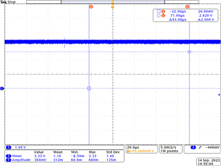
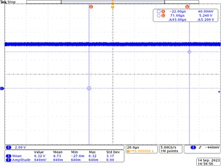
    Please find the attached Vout,3V3 & V7V for your reference

  • Hi Darsana,

    Let me check and get back to you. Thanks!

    BRs

    Lucia

  • Hi Darsana,

    (1) For 3V3 cap, 10uF is good. 

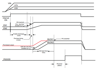
    (2) Soft start capacitor is mainly related with soft start time, but not related with Buck1 and Buck2 sequence, as you can see from below figure. By adjusting the value of CEN, you can control the startup sequence but not power down sequence (as shown below, power down together). If you also need to control power down sequence, MCU is recommended to have external controlled EN or you can consider sequencer IC. 

    Thanks and kindly let us know any further support need!

    BRs

    Lucia

  • Hi Darsana,

    I saw you posted in another thread about same topic. Let's discuss in that thread. 

    Thanks!

    BRs

    Lucia