This thread has been locked.

If you have a related question, please click the "Ask a related question" button in the top right corner. The newly created question will be automatically linked to this question.

UC3843: output skip issue

Part Number: UC3843

Customer was using UC3843 to design a boost with 60Vin to 65Vout, with voltage mode control. They found the output of UCC3843 kept on and off unexpectedly, while the voltage at COMP and ISENSE were stable. Could you please help check the possible reasons? Thank you.

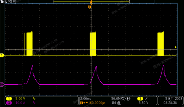
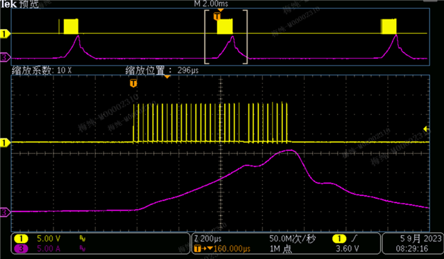
In the below waveform, CH1: pin 1 COMP voltage, CH3: pin3 ISENSE voltage, CH4: pin6 OUTPUT voltage

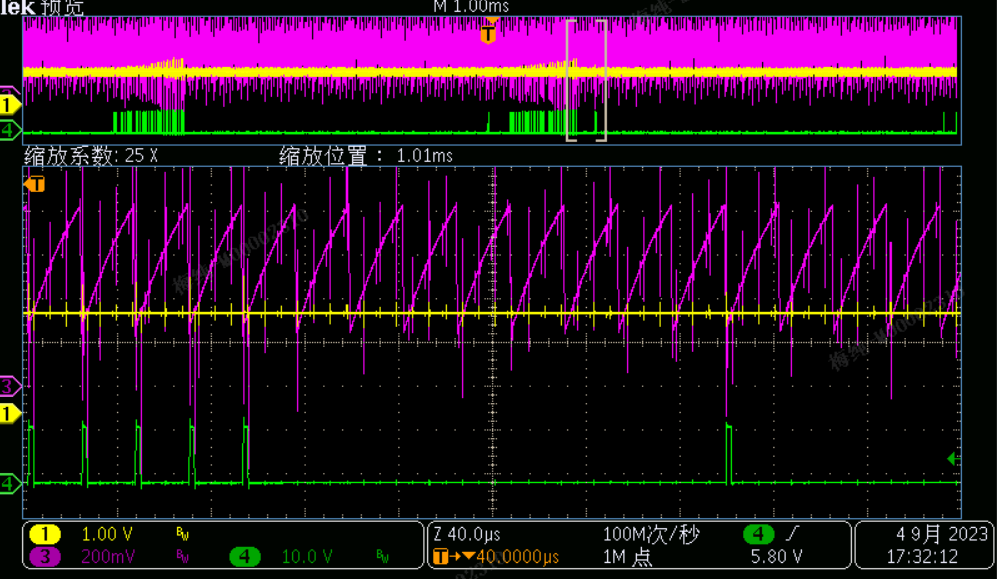
下图中,1通道是1脚电压,3通道是3脚电压,4通道是6脚的驱动输出

  • Aki,

    When you are trying to operate at minimum duty cycle, in the valley of the RAMP and there is significant noise, this can result in missing pulses as you are seeing. Choosing a larger CT and smaller RT can also provide a longer discharge RAMP time which can help to achieve a lower, more consistent minimum on-time (smaller duty cycle).

    Your CS signal looks very  noisy and according to your schematic, the RTCT (Oscillator) is also likely very noisy. Where, exactly are you making your measurement? You should be measuring as close to the IC as possible and using "tip and barrel" probe measuring technique, as shown below. 

    If you are setting up the PWM for voltage mode control please refer to the diagram in Figure 8-13 of the UC3843 data sheet. Also, pleas add a 100 nF high frequency bypass capacitor closest to the VCC pin (pin 7) and in parallel with C132 (4.7 μF).

    Regards,

    Steve

  • Steve,

    Thank you. Please check the further feedback from customer.

    As shown in the following figure, CH1 channel is the driving waveform, and CH3 is the input current waveform. It can be seen that drive loss is periodic, so I do not believe it is caused by noise. This looks like a loop oscillation, but the Pin 1 waveform of UC3843 is stable, so it shouldn't be a loop problem.

    When the input voltage is low, there is no such problem and it works normally. I feel like UC3843 is unable to output a very low duty cycle at this condition.

     For UC3843 used as voltage mode, the solution of using capacitor divided down and fed to the current sense pin is explained in document SLUA257.

  • Have you tried measuring pin1, AC coupled and zoom the amplitude to observe if there are slight oscillations? If you decrease the input voltage or increase the load current does the condition change? Have you tried what I previously recommended to change the RTCT to a larger CT, smaller RT? If you have tried all these and you are convinced the loop is stable, it could be that the PWM is unable to resolve to such a small on-time. If there is an oscillation, is it able to be measured at the DC output voltage (AC coupled)?

    Steve