Because of the holidays, TI E2E™ design support forum responses will be delayed from Dec. 25 through Jan. 2. Thank you for your patience.

This thread has been locked.

If you have a related question, please click the "Ask a related question" button in the top right corner. The newly created question will be automatically linked to this question.

BQ25302: BQ25302 - ICHG PIN Charge current setting ask.

Part Number: BQ25302

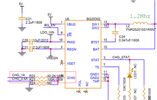
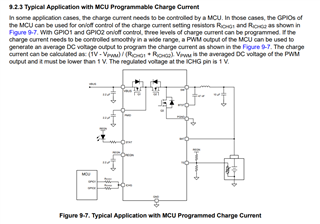
hello. I implemented it as shown in the picture below, referring to "9.2.3 Typical Application with MCU Programmable Charge Current" in the datasheet.
I expected it to work like the truth table below, but it doesn't work properly.(The STAT pin blinks.)

How should I modify the circuit?
Should I use Relay for complete blocking?
Please help.

  • Hello, 

    Thank you for reaching out via E2E. The STAT LED blinking does not necessarily mean the issue relates to the ICHG resistor circuit as a variety of faults will result in STAT blinking.

    For the purpose of debugging have you confirmed the device works as expected if you de-solder on of the resistors so that there is only 1 resistor from ICHG to GND? If you still have issues then that means the issue is not the circuit connected to ICHG pin. 

    Best Regards,

    Garrett 

  • Hello.

    Thank you Garret.

    Normal operation was confirmed when only R24 was installed.

    Are there any problems with the operation truth table and circuit configuration?

  • Hello, 

    Based on your schematic the truth table appears correct. When 40.2kohm is connected to GND ICHG = 1A and when 100kohm is connected to GND ICHG = 0.4A. 

    In the truth table what does "High" indicate in terms of your MCU GPIO function? The ICHG pin should not be pulled up to another voltage rail. When 40.2kohm resistor is connected to GND the other resistor should be floating. I recommend looking into how your MCU GPIOs are functioning. 

    Best Regards,

    Garrett 

  • Hello.

    Thank you Garret.

    R23 : Floating
    R22 : Low

    Even though I gave the GPIO signal like this, it doesn't work.
    Are there any other guesses?

    (Or should I physically disconnect it completely using a relay?)

  • Hello, 

    In regards to debugging the MCU GPIO I recommend testing if the GPIO signal correctly drives the resistor low or floating. To do this I would only having one of R22 and R23 connected to your MCU and also have R24 connected to GND. Test switching the GPIO between the two states and confirm ICHG matches just the R24 setting when GPIO is meant to be floating and ICHG matches the parallel resistance of the two resistors when both are connected to GND. 

    As you mentioned the other option is to use a relay to physically disconnect the one resistor while the other resistor is connected to GND. 

    Best Regards,

    Garrett