This thread has been locked.

If you have a related question, please click the "Ask a related question" button in the top right corner. The newly created question will be automatically linked to this question.

BQ25619E: PG and STAT LED flickers if battery tries to charge above 3.0V

Part Number: BQ25619E

Greetings,

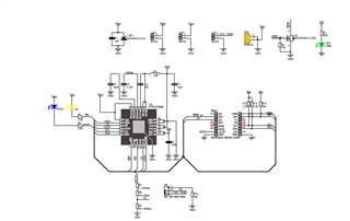
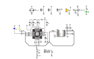
I am using BQ25619E IC on board with following schematic.
I have not programmed the IC and have connected a 2.6V battery. I connected both CE and PSEL pin to ground (GND).

Now, I am connecting USB Board with USB Protection IC as shown in the schematic. The VBUS and GND signals go to the BQ25619E Board.
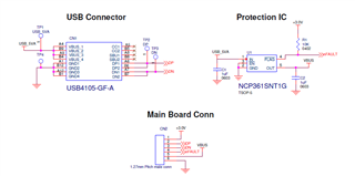
When I connect Adapter, the battery charges smoothly till 3.0V but PG and STAT LED starts flickering when the battery voltage reaches 3.0V. What might be the reason for this?

The USB protection IC is triggered only when the Input current on VBUS is greater than 750mA. But the default settings in BQ25619E for Pre-charge current (40mA), Termination charge current (60mA) and Fast charge current setting (340mA) do not exceed 750mA. So why is there a flickering of PG and STAT LED?

  • Hello, 

    Thank you for reaching out via E2E. PG indicator transitioning on and off is a clue that the issue may relate to your input adapter. If something related to the input adapter was interrupting charge it would make sense that STAT LED is flickering between indicating charge in progress and not charging. 

    Can you please help to provide a waveform showing VBUS, VBAT, and PG pin signal at the time when you observe the unexpected behavior. It would also be helpful if you could read the status of all I2C registers at the time when you are observing PG and STAT LEDs flickering. 

    Best Regards,

    Garrett 

  • Hi,

    Thank you for indicating issue may relate to input adapter, but I have been working with this adapter for a long time and I did not observe this problem previously.

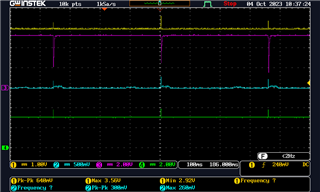
    Below is the waveform showing VBUS (Pink), VBAT (Yellow) and PG (Green) pin along with IBAT (Blue).

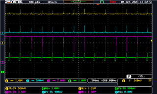
    Zoomed waveform is below,


    I am not programming BQ25619E as I am not using microcontroller. I do not have a provision to read the status of all I2C registers.

    Another observation is, the battery charges well from 2.6V to 3.0V without flickering observed on PG and STAT LED. The flickering of LEDs start only when battery reaches 3.0V and is trying to charge further. What might be the cause this issue?

  • Hi Vedashree, 

    Thank you for providing the requested waveforms. Based on the fact that the battery charges well from 2.6V to 3V it appears the cause of the issue is the device attempting to increase the charge current from 40mA to 340mA. 

    Your waveforms show every time IBAT attempts to increase VBUS drops below the minimum acceptable voltage level for an input supply. This causes the converter to briefly turn off to allow VBUS to recover, hence PG and STAT will change statuses.

    This indicates your adapter may be getting overloaded. You previously mentioned your USB protector limits the input current to 750mA, do you have any load connected at SYS?

    I recommend you take a waveform showing IBUS during this behavior to check if you are reaching the 750mA limit. Also taking a closer look at your schematic you currently do not have any capacitor on VBUS when a minimum of 1 uf is required. 

    Best Regards,

    Garrett 

  • Hi,

    According to your conclusion VBUS is getting loaded with load connected at SYS (VSYS) when charge current increases to 340mA. But I do not have any system load on VSYS.

    In below waveform Yellow: VBAT, Pink: VBUS; Blue: IBUS. (Ignore Green waveform)

    In below waveform Yellow: VBAT, Blue: IBAT; Pink: VBUS; Green: PG

    Yes, the USB protection IC enables fault if IBUS goes beyond 750mA. but in default state fast charge current is 340 mA in BQ25619E and there is no load on VSYS. I do have 1uF capacitor near U1 IC (USB protection IC) output which is VBUS.

    The only thing is PSEL is connected to ground allowing input current up to 2.4A. Will this have any affect on charge current and ultimately dips observed on VBUS? 

  • Hi Vedashree, 

    Thank you for providing the new information.  In the case where output side of BQ25619E is only attempting to draw 340mA it appears the issue will need to be fixed in your physical board design. I do not know what current your USB input is rated for, but its voltage should not be dropping so severely due to approx. 340mA current draw. It is potentially worth checking if your protection IC is in reality limiting the current to a lower value than 750mA. 

    In the past similar issues have been seen where there is too large of parasitic resistance along the cable and PCB trace from the power source to the VBUS pin. You are also free to try driving PSEL high to set input current limit to 500mA rather than 2.4A, but for your specific case I am not sure it will make a difference given that input current should be well below 500mA when ICHG= 340mA. 

    Best Regards,

    Garrett 

  • Thank you for the information.

    The USB adapter I use is Raspberry pi USB C power supply.

    • 5.1V / 3.0A DC output

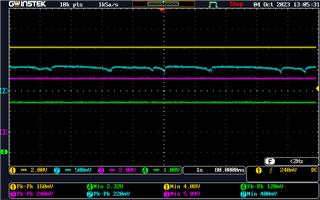
    I have taken waveforms without USB protection IC present (Only BQ25619E IC and USB Connector with VBUS directly connecting to IC). Below is the waveform.

    Yellow: VBAT; Blue: IBAT; Pink: VBUS; Green: PGOOD when PSEL is LOW.

    Blue waveform represents current where 500mV = 1A. Here IBAT is greater than 500mV so the charge current is approximately 1.2A. This is not the default fast charge current 320mA. I'm suspecting that as the current drawn is greater than 750mA for fast charging the USB protection is enabled by IC when it is present in the circuit.

    Another observation is when we connect PSEL to HIGH (pull up), the charge current never crosses 500mA. So can the ICHG default will be overridden by PSEL status? 

    What do you suggest?

  • Hi Vedashree, 

    The new waveform provided confirms the issue was related to the USB protector as VBUS no longer drops due to the increase in battery current draw.

    When PSEL is high IBAT never crossing 500mA is expected because input current is being limited at 500mA. PSEL to HIGH sets Iindpm setting to 500mA, but does not change the ICHG setting. For example if Iindpm = 500mA and ICHG = 1A IBAT will not reach 1A and REG0A status register will indicate the device is in Iindpm status.

    You mention you are not using a microcontroller. Therefore as long as I2C communication is not being used ICHG should not be changing from 340mA default. It appears ICHG register is either being unintentionally modified, or resistor value accuracy is affecting your IBAT measurement. 

    I would need to see status of ICHG register (REG02) to confirm if this setting has been modified, but based on your previous response I understand you do not currently have access to read registers. 

    Best Regards,

    Garrett